My old Alesis DM Pro has been great for the testing of the drum and trigger designs, but does not have nearly enough general purpose inputs for a large percussion instrument (several of the inputs can only be used for cymbals or hi-hats). I did consider a small stack of relatively inexpensive commercial units, the Ddrum DDTI being a strong contender. This would still need an outlay of ~$1000 and would require the merging of multiple MIDI streams externally or inside the computer. In keeping with the DIY aesthetic of my 3D printed drums and triggers, and the fact that I don’t have $1000 to spend on trigger interfaces, I have decided to use an Arduino for the trigger module.
The Arduino has a fixed number of input pins that can be used to measure the outside world. The Mega that I have been using is unusual in having a luxurious 16 inputs available (5 is more common). Unfortunately that is still not enough and the Mega has another problem that is the real deal-breaker – it cannot act as a USB-HID (HID: Human Interface Device) peripheral. USB-HID peripherals such as keyboards, mice, and game controllers are designed for human interaction with computers. They use a standardized protocol that allows for plug-and-play functionality, meaning the device can be recognized and used by the computer without needing additional drivers in most cases.
MIDI from Non-HID Arduinos
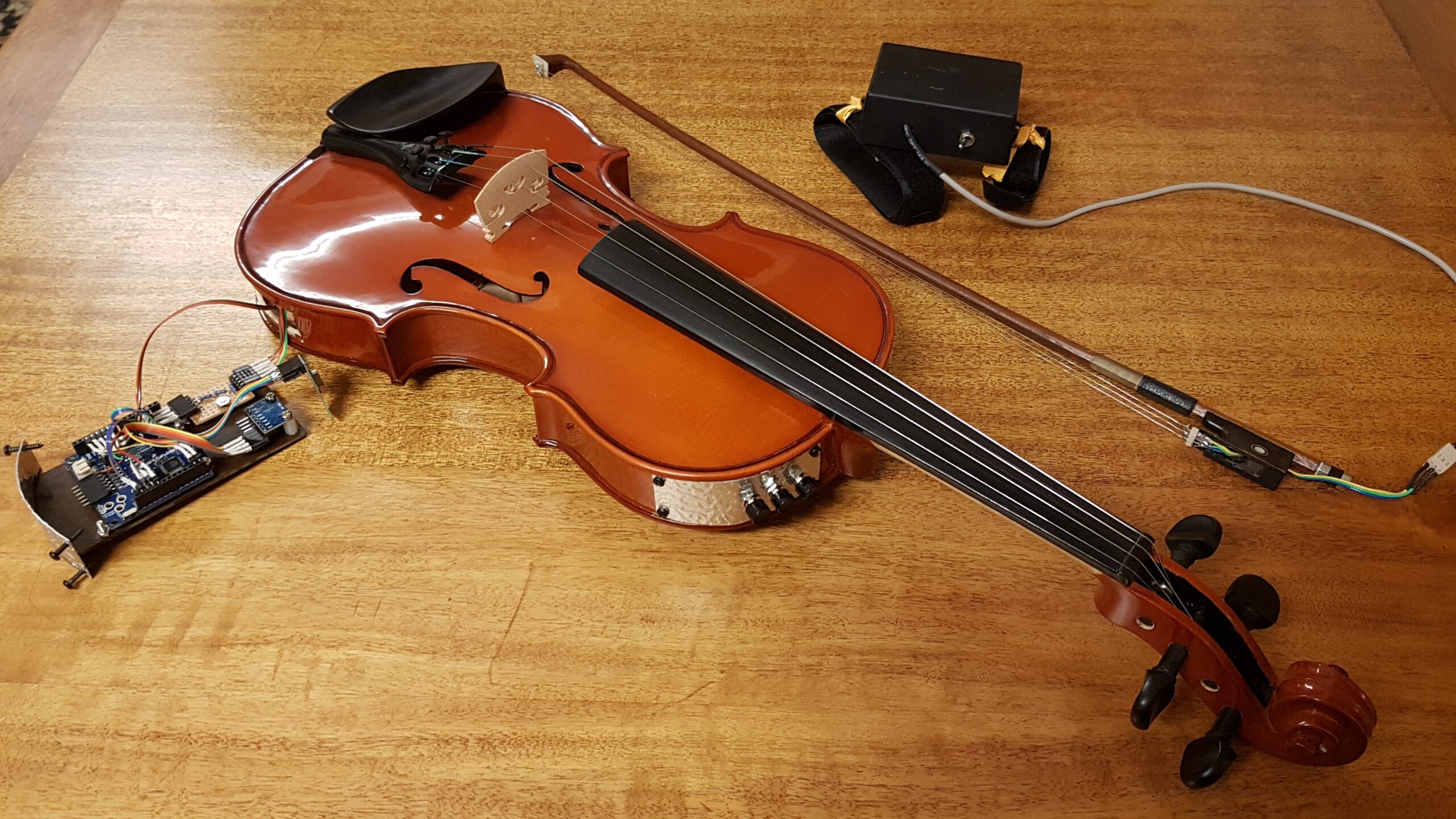
The Mega has a USB port that it uses for loading programs and communicating with your computer via a USB-serial connection. This USB-serial can be turned into MIDI by a program called ‘Hairless MIDI‘. The image on the right shows a Bluetooth connected Arduino powered instrument (my nichrome strung Arduino violin), connected to the MacOS MIDI bus. For the Tonnetz drums project, each octave has an independent MIDI controller. I need to some way of merging the MIDI streams from the drum octaves, which is not possible with Hairless (only one copy of Hairless can be running and each copy only accepts one serial input).


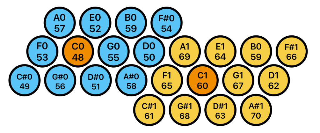
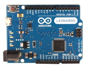
I would also like to connect the drums to other MIDI devices, such as iPads, where Hairless MIDI is not available. I decided to retire my Mega in favour of a slower, less capable, Arduino with a special feature – the Leonardo. The Leonardo can become a USB-HID device, one that MacOS (and others) will accept as a USB MIDI interface, just like plugging in a MIDI keyboard. I decided to split the drumset processing in to two octaves with a Leonardo for each. This design will make it easier to use a cut-down 1 octave system when space is tight, make the wiring more compact by putting each controller with its own octave, and reduce the processing load on each Arduino (in comparison with handling the whole array in the Mega using a multiplexer).
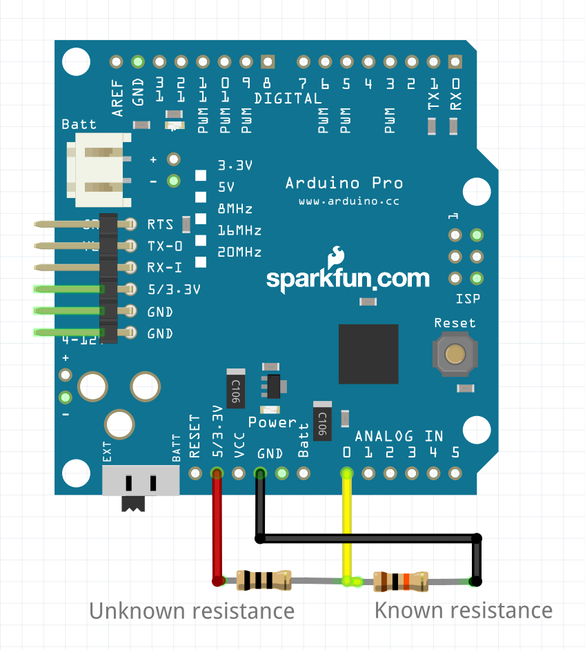
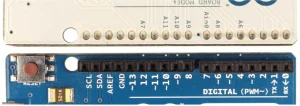
The Leonardo has another trick that makes it very suitable for handling an octave of drums. It appears, from the silkscreened pin descriptors on top that is has 6 analog input channels; A0 – A5. If you turn the Arduino over and read the back, digital pins 4, 6, 8, 9, 10, and 12 double as analog inputs A6, A8, A9, A10, A11, and A7 (in that order). 12 inputs, just what I needed. My own Leonardo is a cheap clone from Jaycar without the underside labels, so I have to look at pictures of genuine ones to see the extra pin assignments.


Electrical treatment
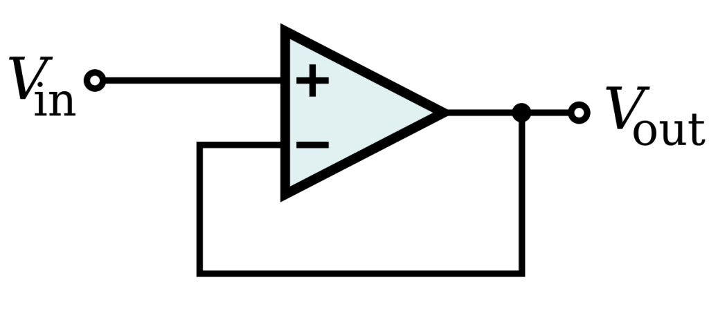
The Buffer
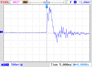
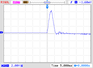
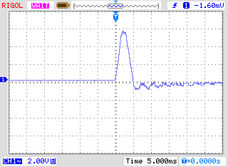
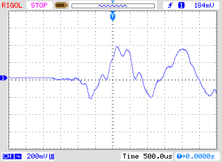
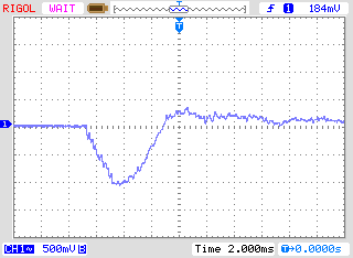
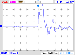
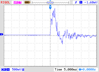
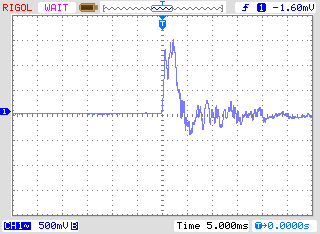
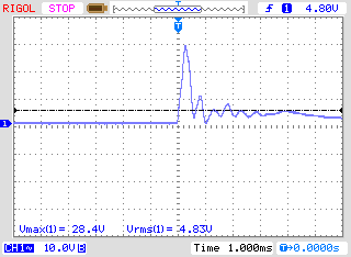
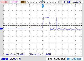
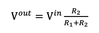
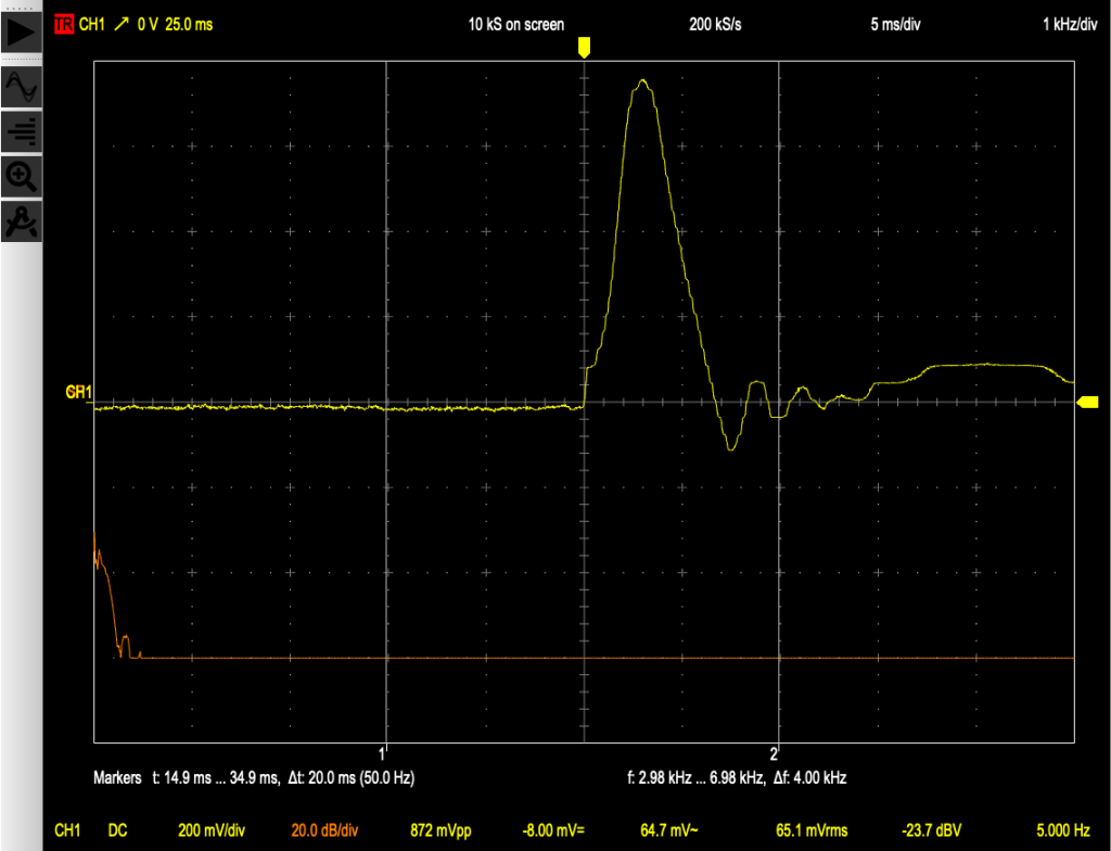
We have seen in an earlier post, that piezos can generate voltages high enough to potentially damage Arduinos. This is less likely when the triggers are mounted in the drums (on measurement, voltages are considerably lower), but it is still prudent to protect the central controller for the system. To present a better signal to the Arduino, I decided to buffer all of inputs with inexpensive quad opamps (in this case, the LM324 operational amplifier). These amplifiers are set up for ‘unity’ gain – they simply present to the output what they see at the input, with three important changes. Firstly, the output impedance is much lower (better for the Arduino for technical reasons) and the output voltage cannot exceed 1.5V less than the power supply for the amplifier chip itself. By supplying the opamp with 7.5 Volts, the signal can never exceed 5V. Lastly, in the configuration used below, the opamp cannot amplify a negative signal, protecting the Arduino from ‘ringing’, a negative voltage sent by the piezo as it recovers from the transient of the initial strike. When testing candidates for trigger elements, I have seen ringing voltages approach -3V.
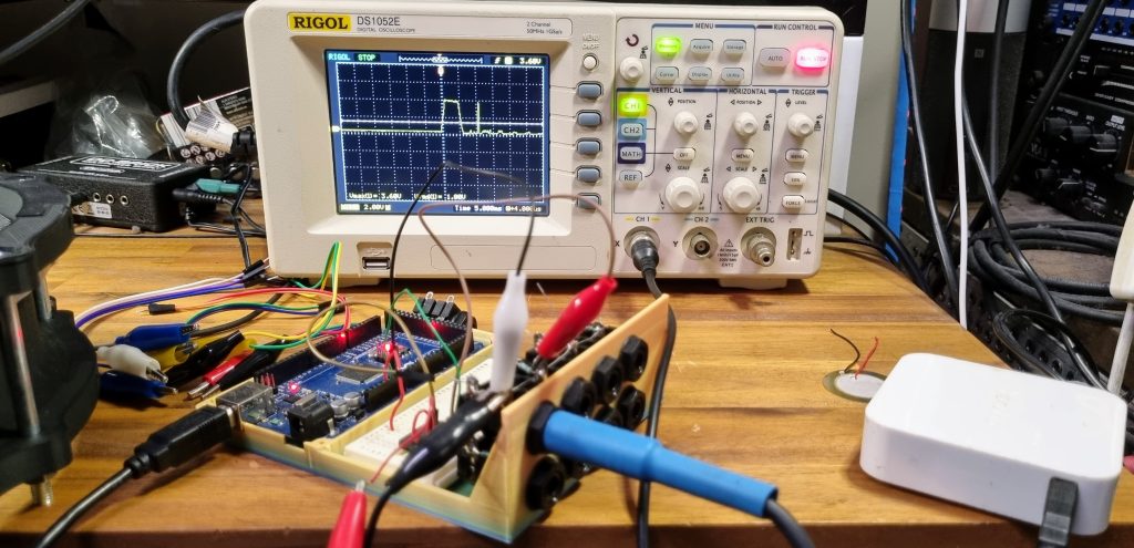
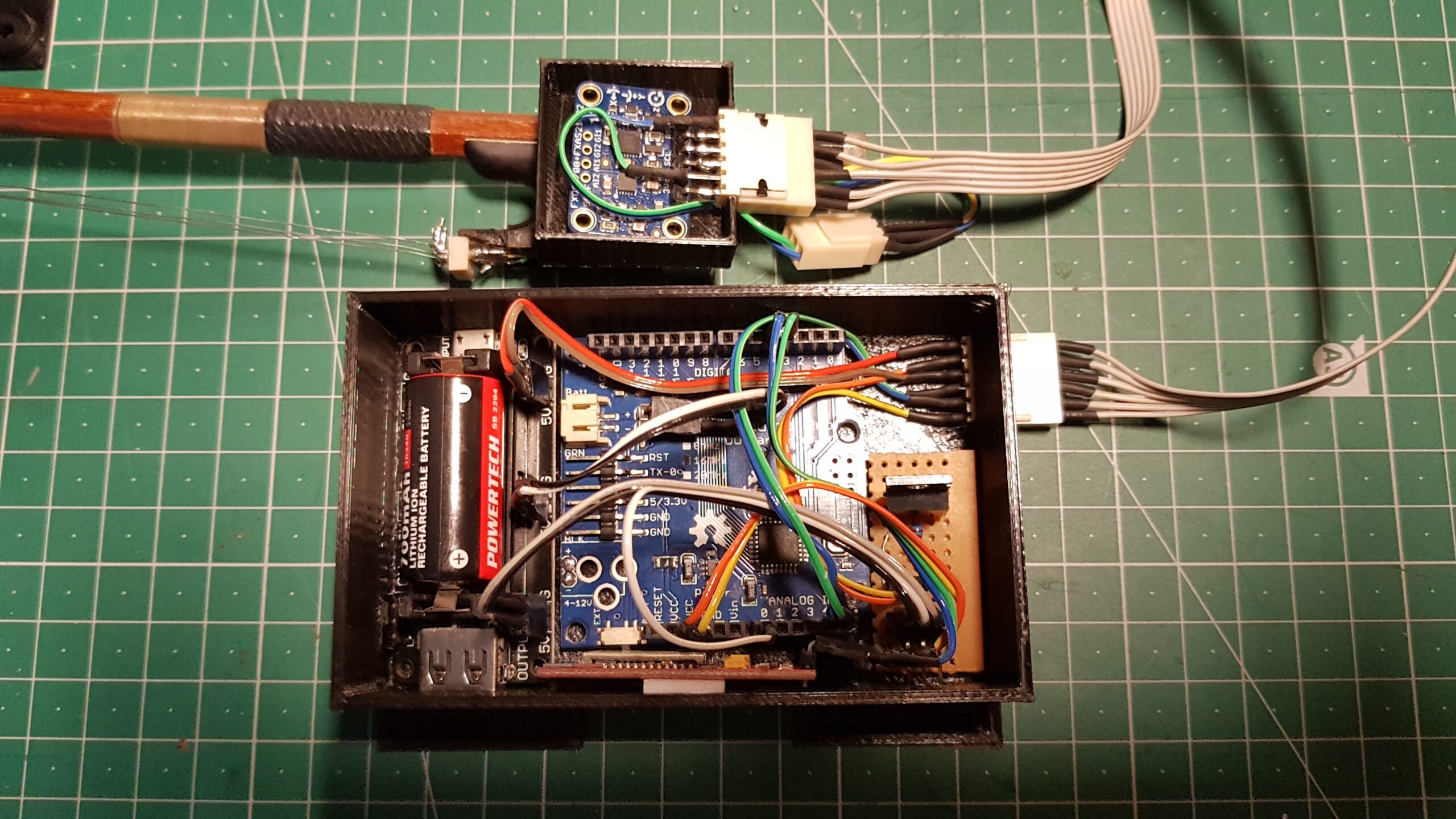
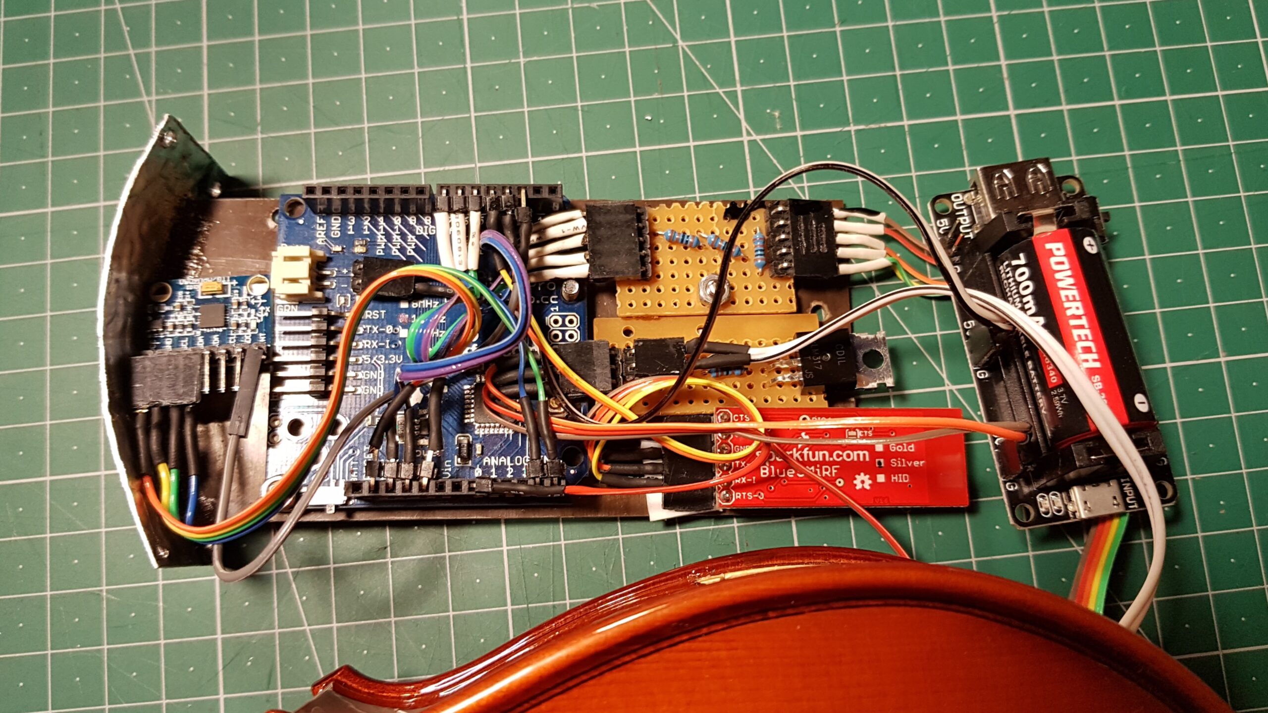
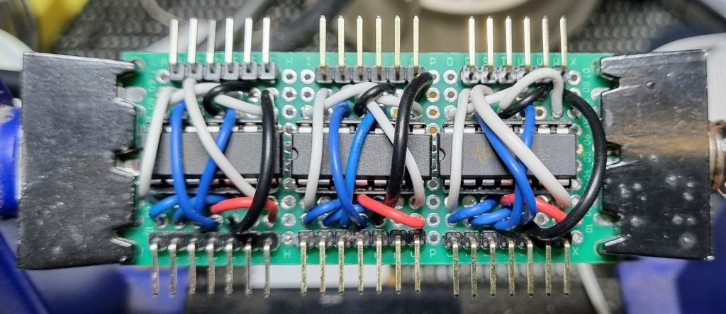
On the right is the buffer layout I hand-wired on prototyping board. Manual wiring like this can be time consuming and error prone but is useful for prototyping as it requires minimal materials and, in comparison to ordering a custom printed circuit board, it is far easier to fix small mistakes.


The Whole Controller Module
This is not the way I would recommend this system be implemented now that the design has been tested and shown to work. A sensible approach would be to develop a single PCB to hold the buffers and the other input conditioning, saving hours of wiring work. It is, however, an implementation that can be attempted for very low cost, without specialty PCB designing software.
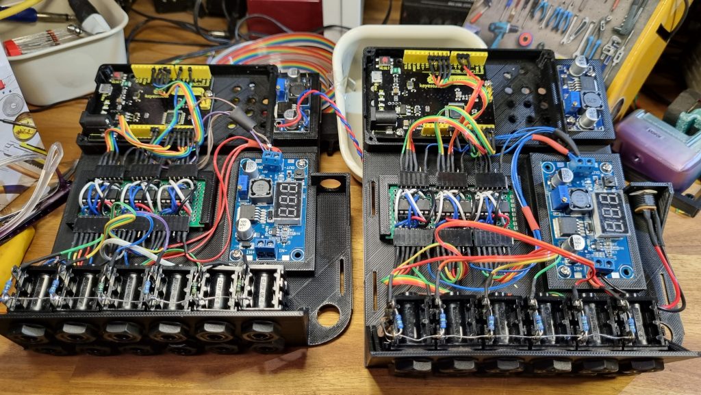
A more advanced designer might also use a bare microcontroller instead of an Arduinio, saving more time and money. Unfortunately I have neither time nor money to spare. I have to keep the system modular and, where possible, made from parts I already have available. The Arduino, buffers or input board from this project might be re-used in several more projects and so must remain discrete, modifiable, and accessible.
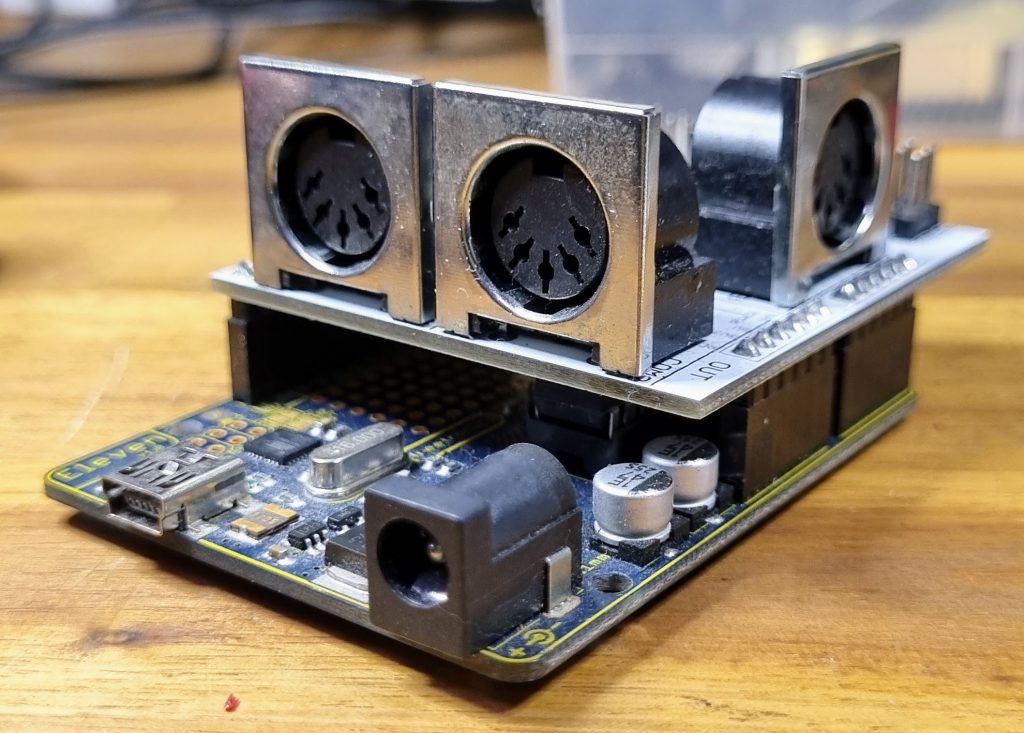
Two DC-DC voltage converters (the blue modules) power the project. The large converter with the digital display supplies power to the opamp module – the display allows for rapid adjustment on-the-fly without a multimeter. This is desirable because the opamp voltage effectively sets the upper voltage limit, and hence the maximum MIDI velocity, that can be processed by the controller. The smaller module can power the Arduino. This is intended to allow the controllers to operate without a computer attached, sending MIDI via a 5-pin jack mounted on a MIDI shield. The Leonardos are currently powered via the USB connection that sends MIDI to the computer, so these DC-DC modules are not wired in. The required voltages are regulated down from a 9V plug pack.
The 3D printing file for the controller base and the MIDI transmission software for the Leonardo are available from the project download page.