
It isn’t hard to make a DIY e-drum system that ‘sorta’ works, but there is a much longer road to making one that is good to play. The Alesis DM Pro that I have using is the latest of a series of Alesis products that I have used for processing my home-made drum pads. I’ve also owned a DM10, DM5 and a DM4. My very first E-drum unit was an ancient Roland PM16. All of them gave a far superior ‘feel’ to just sticking peizos straight into the Arduino analogue inputs. This direct approach has problems detecting some triggers, strange velocity response and crosstalk (one input setting off other adjacent drums) even when only one drum is plugged in.
We are using roughly the same hardware components, my old Tama Techstar pads were just piezos glued to plywood, so what is going on and how do these commercial products make it work so well? To get a more predictable, stable drum we need to improve our handling of the sensors. Look at the oscilloscope captures below, particularly at the Vmax(1) at the bottom of the images.
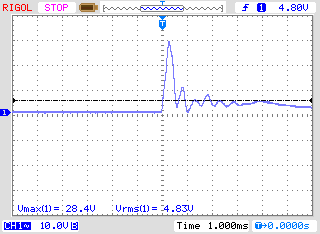

- Piezos can damage your Arduino. A piezo, struck hard, can send (depending on the model) 10, 20 or even 30v down a line that would really rather be seeing about 5v. We need to limit the voltage to safe levels.
- Piezos are the wrong impedance for easy sensing. The Arduino wants to measure from a low output impedance (~10KΩ) but it is currently seeing about 1MΩ from the input resistor. We can fix this by adding an active buffer (or putting a lower value resistor across the input, but this will reduce sensitivity).
- Commercial products have gain controls (usually electronic, but the PM16 had tiny potentiometers), velocity curve selection and crosstalk detection. These are software solutions and shall be addressed later.
For the sake of simplicity and getting a system up and running quickly, we can use a unity buffer to protect the Arduino and condition the signal.
Opamp Buffering
A unity amplifier is one of simplest ways to use an opamp – you just connect the output of the chip to the negative input, as shown below. Any voltage coming in will be mirrored to the output.
The LM324 is a quad opamp that can operate at low voltages. Output cannot go higher than Vcc – 1.5V (1.5v lower than the voltage you are using to power the opamp), but that should still be enough for testing. If we run it from the Arduino’s 5v out line we will still have 3.5v of room to play. If everything works out an independent power supply can be arranged at a higher voltage to allow a full 5v output.
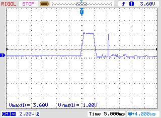
The oscilloscope screen pictured on the right shows the voltage from the drum hitting 3.6v and flattening out for the duration of the hit. This behaviour can be used to our advantage.

Is this good enough already?
Experimentation with an 8″ drum showed that a lot of expressive playing happens below 3.5v with the hard voltage limit acting like an audio compressor – hard hits are effectively flattened out to similar velocity values, smoothing out runs and fast rudiments. The Arduino Mega also has the ability to use a range of reference voltages for measuring input on the analogue lines. We can set the Mega to measure against 4.3v (the closest preset available) instead of 5v or supply 3.5v to the input reference pin to get a full velocity range from our sensor. We could also just use a 3.5v Arduino like the ESP32 that expects a maximum of 3.5v input, but in that case we would have to find a 5v source from outside the Arduino to run the opamp. We could also just adjust the velocity range in software but we are still losing precision and my work on the sampling violin showed that after you account for a reasonable noise floor that loss of precision really does matter. The biggest problem I found was sitting down at a drumkit is a very different experience from hitting a drum in front of an oscilloscope; what I thought was a reasonable velocity range in lab testing was nowhere near the velocity achieved in real playing. All of my hits were flattening out on the 3.5v rail, giving a very artificial drum-machine like feel to performance. This is not good enough, it feels lazy to leave it half-baked like this, and I’m going to need a lot more drum inputs than even the Mega can give me so we might as well do the inputs properly while working out the multiplexers than can give me 8 inputs per analogue channel.