Everything was going so well. I had worked out a fast, repeatable way to churn out triggers for my 6″, 8″ and 10″ printed drums. All I had to do now was crank out about 30 of them for my massive drum array. Then I made three triggers in a row that didn’t work. Some others only worked intermittently, when struck directly on the cone, or returned very low voltage. Something was wrong – something new that only showed up when I started the production line. My very first triggers were still working with no issues apart from a bit of variance in sensitivity that could be dialed away in the drum brain. So what went wrong? I had some hypotheses:
- Bad piezos. They are the cheapest of the cheap .. but the distribution of failures does not seem to support this. My triggers were working, then most of them were not. That suggests a problem with my manufacturing process. Also, I would be shocked to find that the expensive and the cheap piezos were actually coming from different factories, not just identical units priced for their destination market.
- The sensors are flexing too much, damaging the piezo material. I have never been able to experience a real trigger from a commercial product because I am too poor to waste money buying one – everything I’m doing is experimentation and guesswork. I don’t know exactly what stiffness of foam is used above and below the sensor and it is possible that the hard foam cones are transmitting too much force to the disc or not supporting them properly underneath. I do have some early sensors I made with soft foam that are working very well, but they are fitted to 10” drums where I used the soft foam to compensate for the large travel of the mesh ‘skin’. I switched to using hard foam because the soft foam was impossible to shape with power tools and did not respond to a hot wire cutter.
- The adhesive on the foam sheeting is too strong and is damaging the sensors. It is impossible to open up any of my failed sensor packages – the adhesive tears the packaged piezo off the baseplate, leading me to think that the adhesive might be doing the same during assembly or when in use. Commercial products use 3M adhesive sheets that seem just as powerful, but if they are attached to softer foam this might not be a problem. I have also seen instructional videos where the foam cones on Roland drums were changed and it is possible to remove those without destroying the underlying piezo. This one seems plausible.
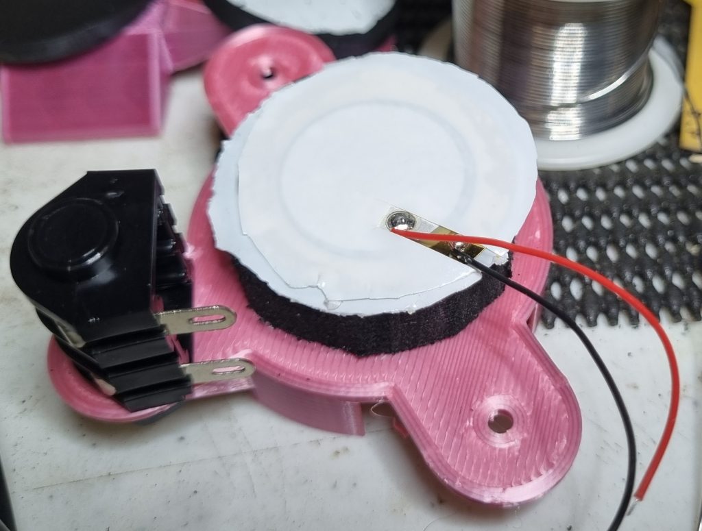
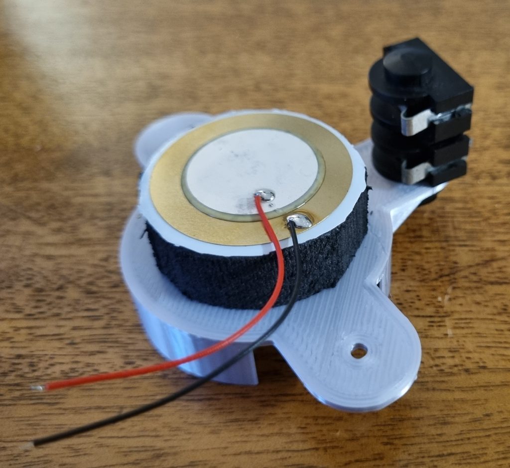
- I purchase piezo elements with leads already soldered on. The solder joints are sufficient, but have huge solder balls. It is possible that the strong adhesive is attaching itself to the piezo around the solder balls when I press the stacks together, then damaging the attachment point when I let go (or when hit during normal operation). Official and third-party replacement cones have little channels cut in the cone to accommodate the lead attachment points but I have not been very consistent with my hand-cutting of the relief channels in my own cones (foam with strong adhesive attached is hard to cut reliably with anything. Even scalpels are fouled by the adhesive).
These effects are linked by the physical properties of the system and may affect the outcome collectively or independently.
Now I can try some experiments to see if I can pinpoint what is going wrong. I can’t do any forensics on the assembled triggers as they cannot be taken apart without destroying them. There are, however, a few things I can try at the design phase to sort out what the problem is.
Trigger Assembly and Testing
Make the foam cone from softer materials.
This could help with:
- Flex or shock damage by reducing the forces on the piezo transmitted from impacts on the drum head.
- Possible adhesive damage – the soft foam is not held well by adhesives so it is unlikely to damage the piezo by pulling it apart.
- Possible damage to the solder attachments or surrounding material – the soft foam will not exert a high degree of force around the sensitive areas.
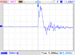
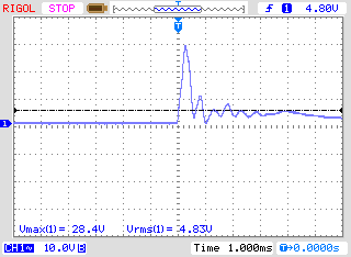
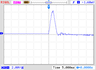
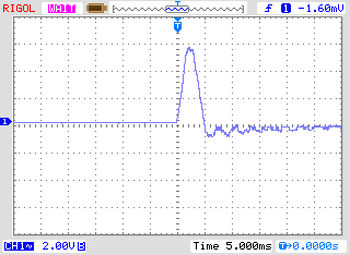
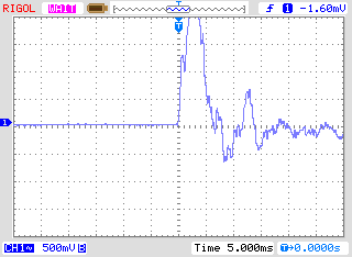
This sensor works – I’m not surprised, I’ve built them before, but I have not directly compared them to sensors made with hard foam. I was not expecting the voltage peak to be this low. This may be from the reduced travel of the 6″ drum skin in comparison to the 10″ I have been using with these softer cones. It may be worth trying to source another foam that has a hardness somewhere between the two I am already using. This foam also has a lot of trouble staying attached to the adhesive on the top of the piezo. In the 10″ shell these soft cones eventually detach from the tape and ‘walk’ out of the drum as they are hit. This is not the design I need.
Reduce the flexing of the piezo
This could help with:
- Possible damage from the cone adhesive when the piezo moves
- Damage to the piezo from flexing with impacts
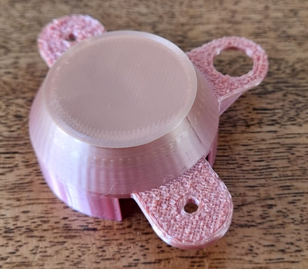
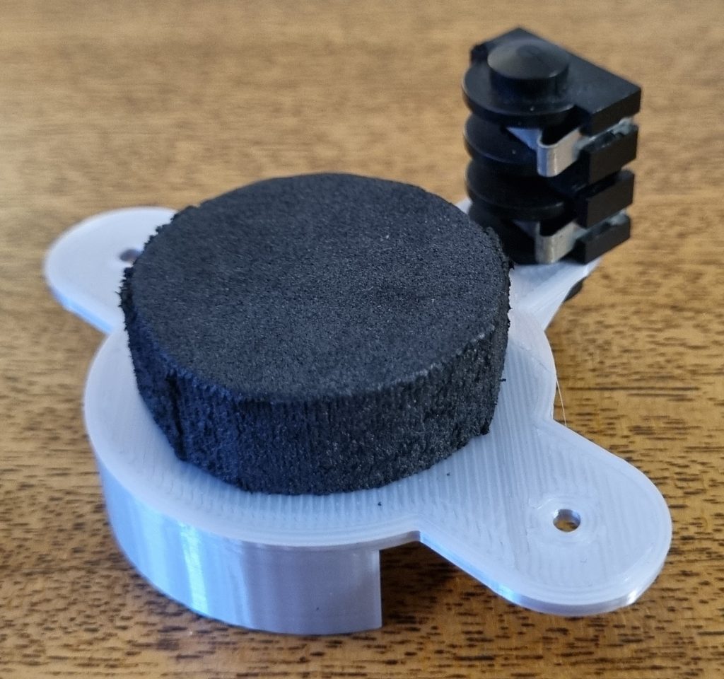
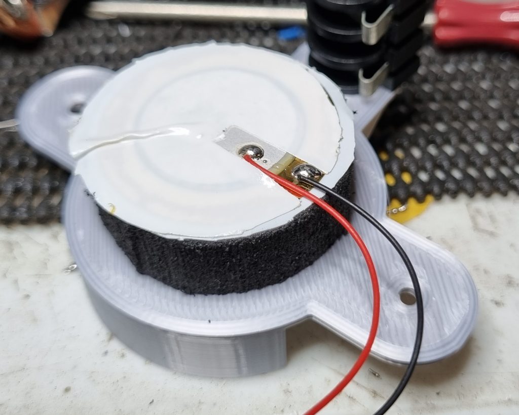
I have designed a new sensor base that replaces the bottom 6mm of foam (the layer directly under the sensor) with solid plastic. The piezo will mount instead to a length of 2mm think double sided foam tape. I expect that this will drastically increase cross-talk by reducing the isolation from neighbouring pad vibrations, but that can be addressed in software.


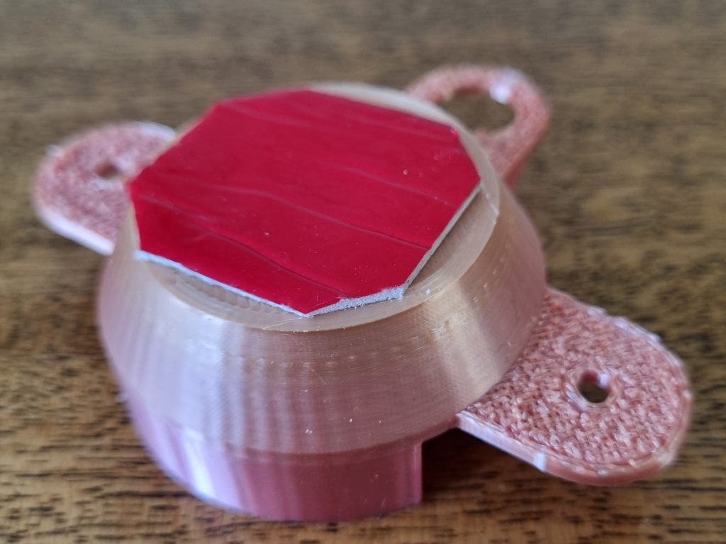
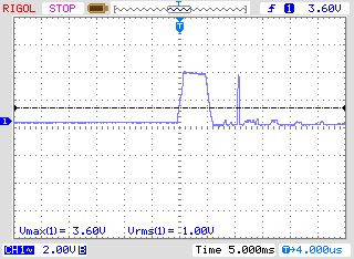
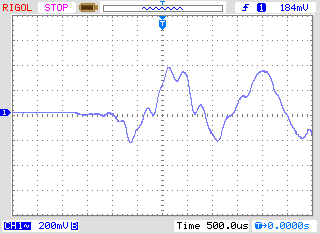
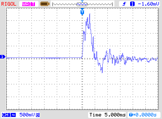
This sensor package is working well, delivering good voltages when installed in a 6″ drum. Curiously, although it supplies an almost identical peak voltage to the normal sensor with a foam base, the oscilloscope trace shows a very flat recovery from the drum hit with almost no bounce or ringing. A possible interpretation is that sensors made with a foam lower disc store and return energy, allowing the piezo to flex (flexing also returns voltage from a disc piezo). This is worth looking into further, but with 24 drums in one array, total crosstalk and transmitted noise from the mounting brackets could become a major issue.
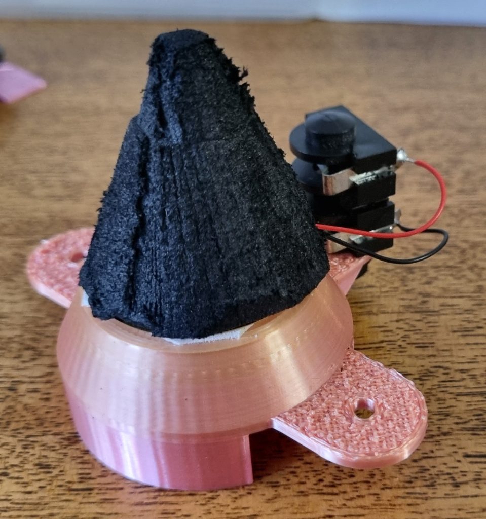
Assemble the cone upside down
This could help with:
- Possible damage to the solder attachments or surrounding material from the powerful adhesive on the bottom of the foam sheet.
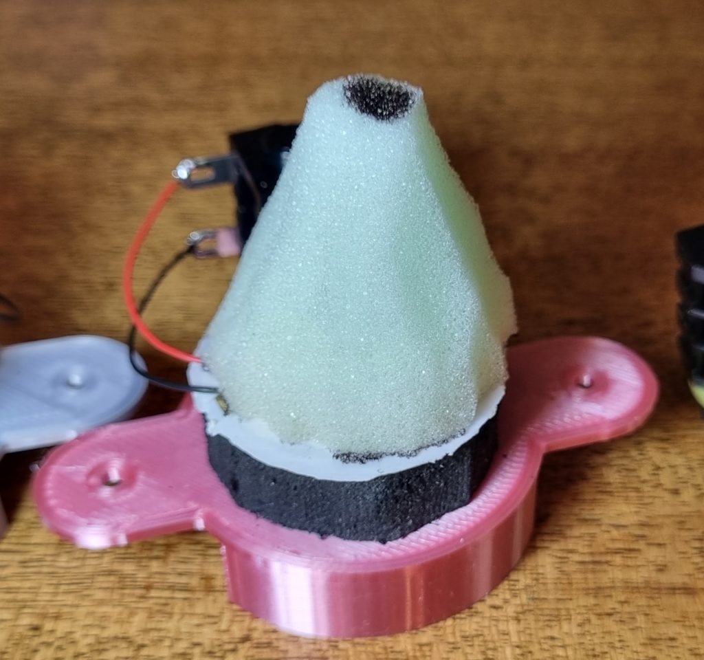
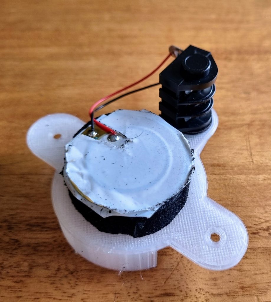
The top cone is made of three layers of foam sheeting. By assembling it upside down (with the adhesive layer on top) I can attach the bottom of the cone using the much softer and weaker Bear tape (with a hole cut out for the solder joints and leads). As a bonus I can use the adhesive on the top layer to add some material that protects the tip of the cone that rubs on the mesh drum skin. I made a sensor like this accidentally when I was working out the manufacturing process and it has been working flawlessly on an 8” drum.
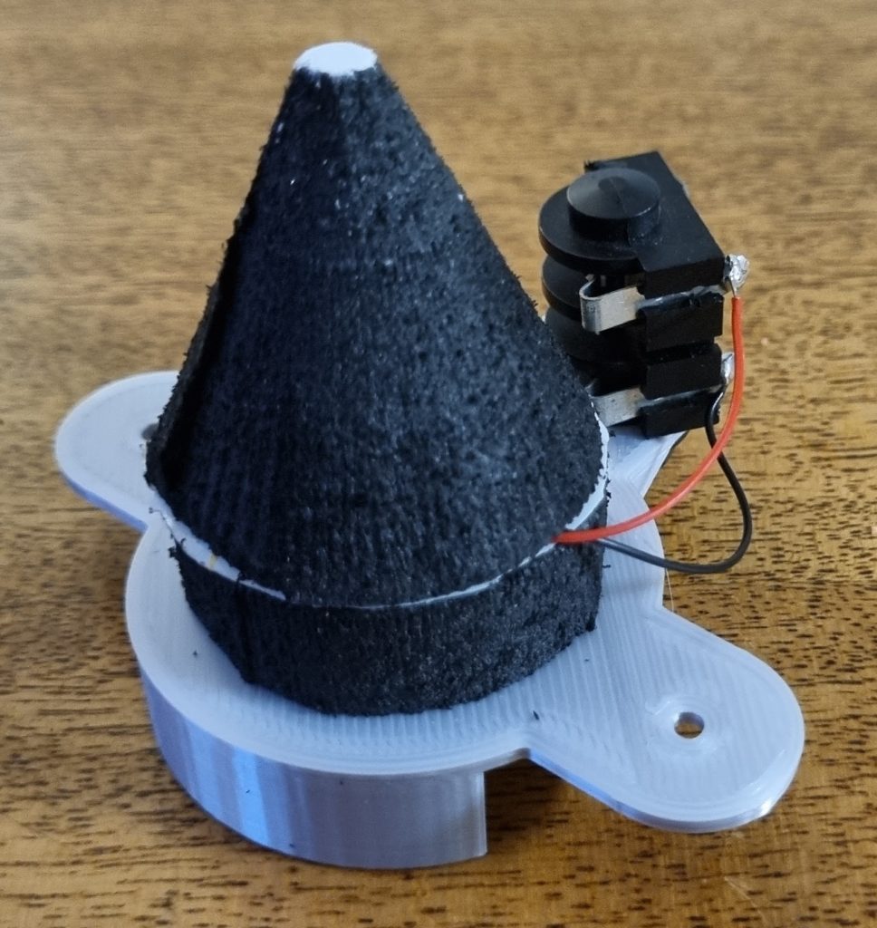
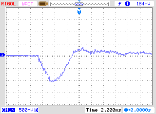
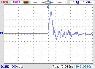
This is working just as well as my normal designs. The vibration after the initial impact is interesting but falls well below the threshold of hit detection.
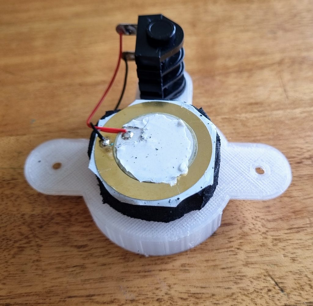
The piezo in this design is sandwiched between two layers of thin, soft and slightly stretchy double-sided tape with a generous cut out for the sloppy factory soldered leads. As usual, the cone base has a channel cut for the leads though this may not be necessary when the cone has no adhesive. I’ll build some more in this design and see what works.
A Note from the Future
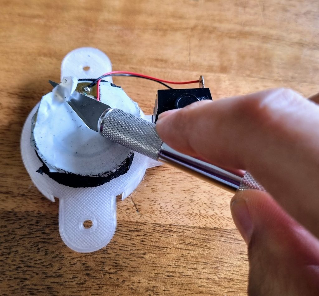
Several months after writing this whole page I started experiencing problems with the triggers again, and made a new discovery – the lower adhesive of the Bear tape was necessary for the survival of the piezo (and does allow for the replacement of the foam cones without destroying them), but in the photos above I am using far too much tape on top of the sensor. The tape should only cover the central disc, not the whole unit. I had to perform remedial surgery on all 24 triggers, as shown below. I also added a 330kΩ resistor from the positive of the piezo to the Cliff sockets. This forms a voltage divider with the 1MΩ input resistor that effectively lowers the input by 1-2 Volts, a much more comfortable range for the buffer circuit that follows.
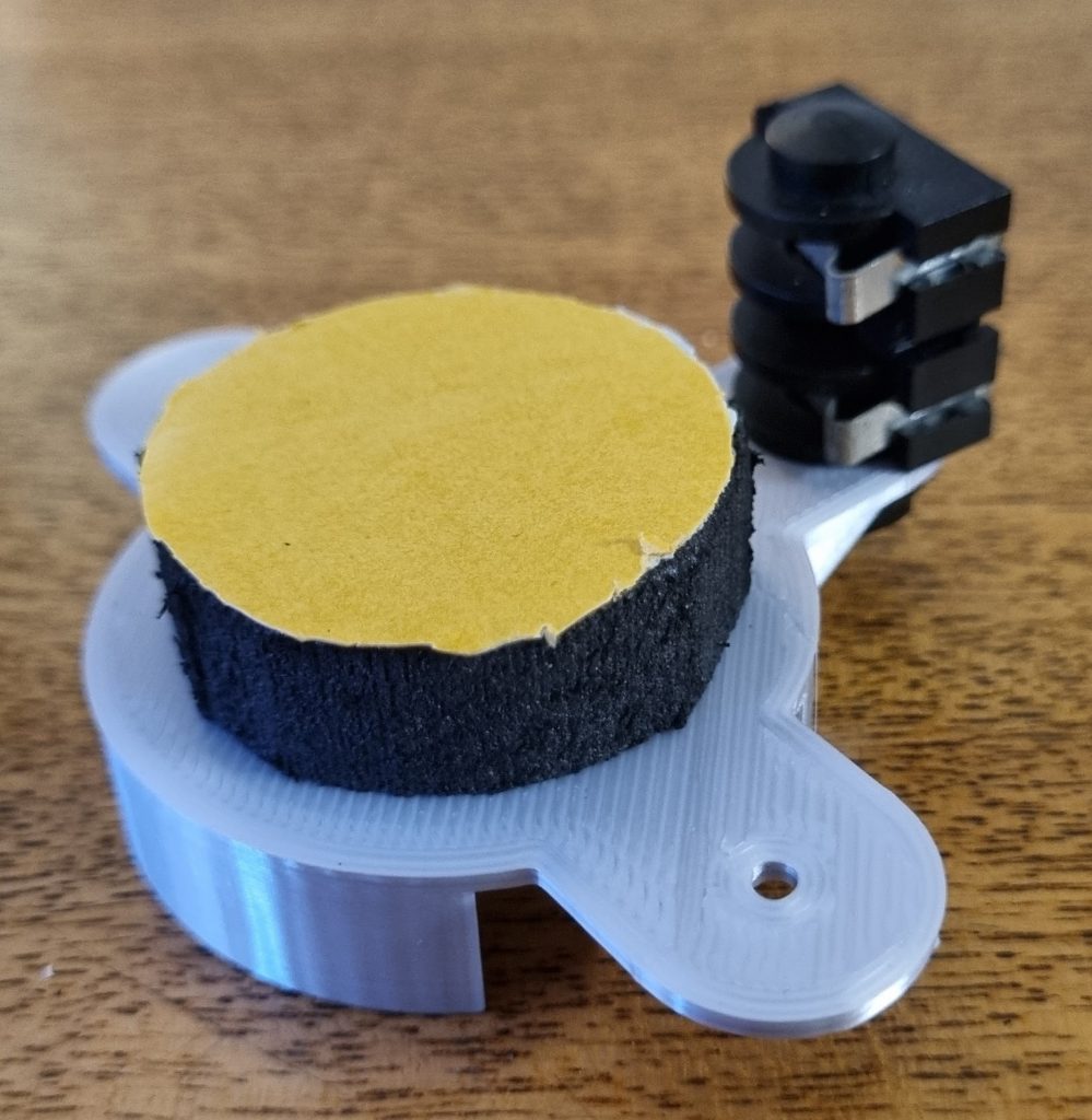
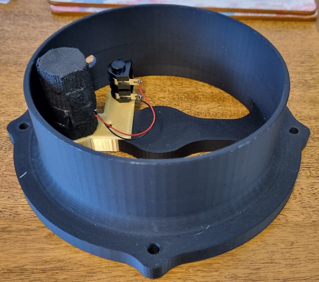
Side mounted sensors
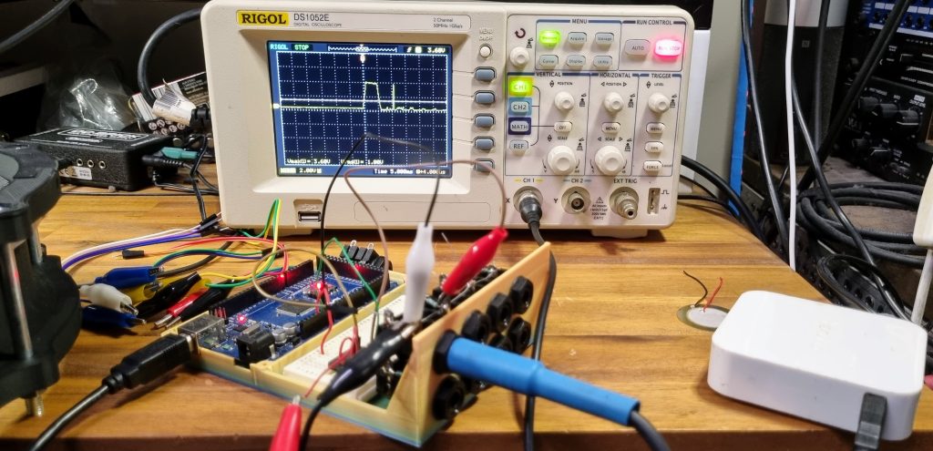
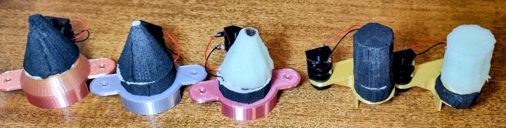
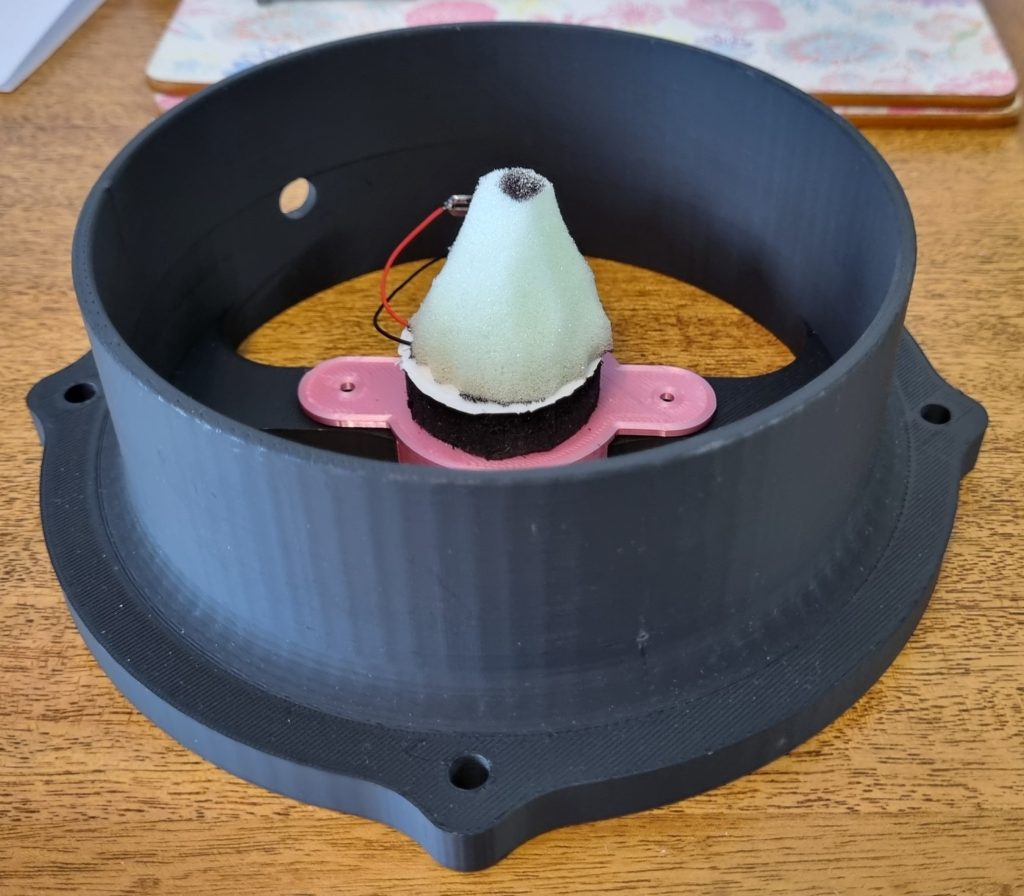
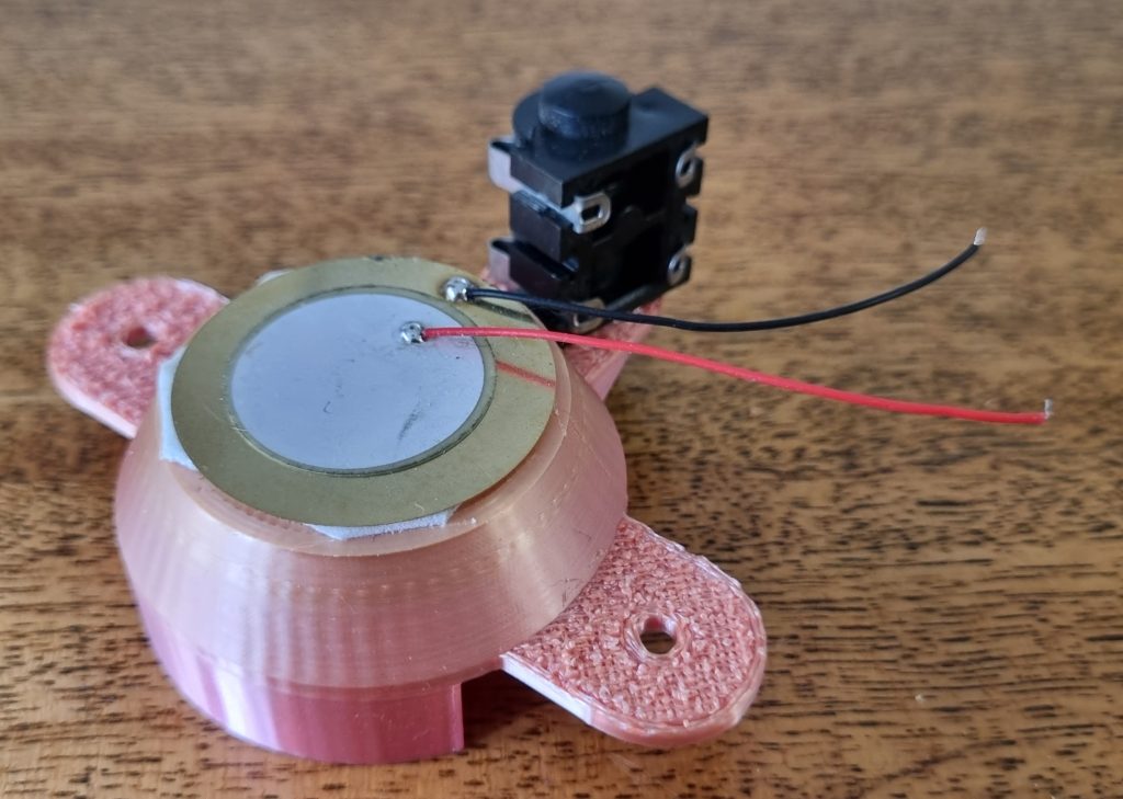
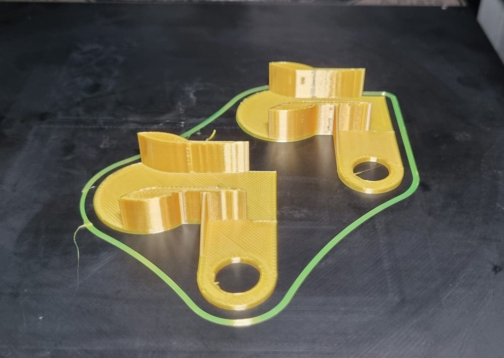
I recently found an old Roland pad in a music shop, a PDX6 or 8, and saw that the sensor in this model was mounted at the rim of the drum, with a flat-topped cylinder of foam contacting the skin. My current practice of mounting a cone shaped sensor in the middle of the drum should guarantee an even response around the drum head but if any hits land on the cone tip, they blast though regular playing at 100% velocity. A side sensor might fix that problem and side-step some of the issues described above that might originate in mechanical stress. A drum head deforms the most in the centre so a side mounted pickup should see much lighter impacts, less flex and less travel overall. I designed some side-mounting fittings and put together test rigs in soft and hard material. These sensors used a pack of smaller 25mm piezos from an earlier project.
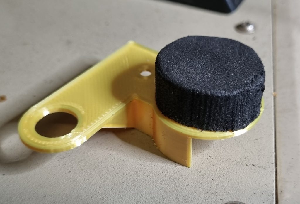
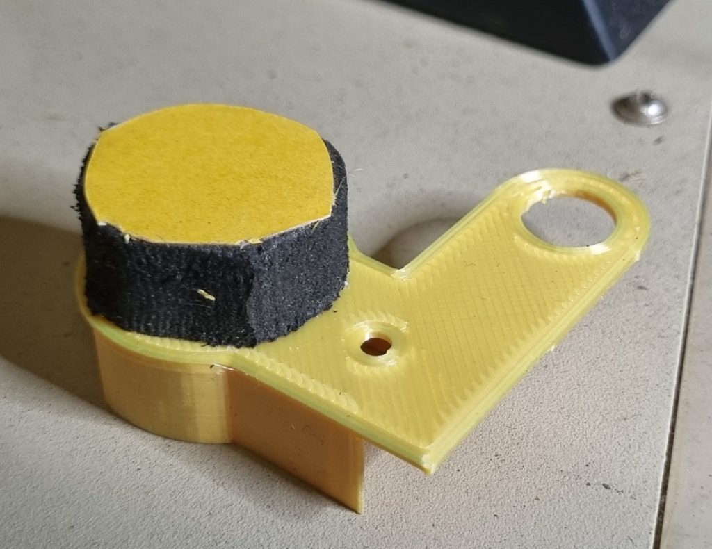
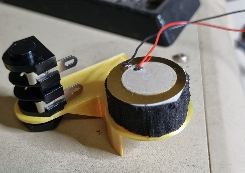
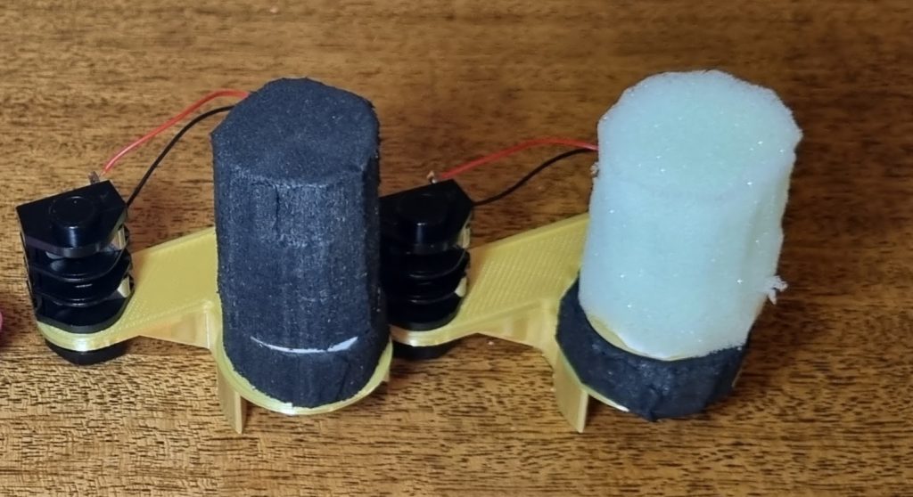
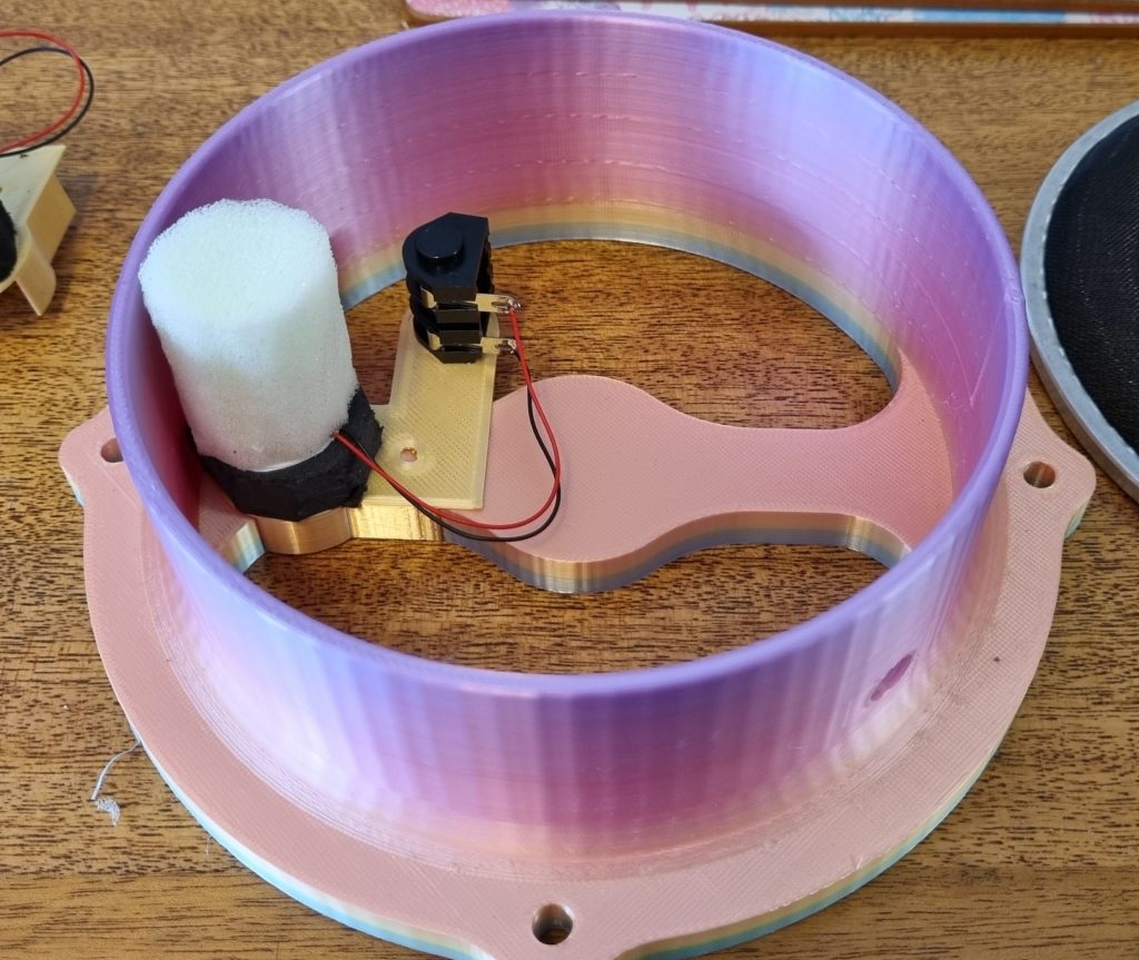
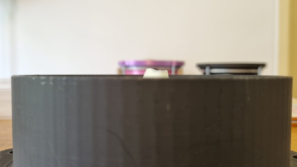
I was expecting lower voltages from the side mounted sensors. They were smaller in diameter (25mm vs 37mm) and the side mounting would transmit a lot less of the stick energy to the piezo. I was not expecting numbers this small. The cylinder of soft material was useless, my hardest hits were just touching 0.5V. The harder cylinder was more promising, giving me ~1V, inexplicably negative. The wires were correctly installed on the piezo and correctly connected to the Cliff jack. This piezo just wanted to be different.
From watching a repair video for the PDX8, I can see that the side mounted piezo element in that pad is much closer to the skin than in my far deeper, more drum-like design, with a much shorter cylinder of foam. I also noticed that the replacement foam does not have a channel for the solder attachments, so they do not seem to be concerned that the adhesive will damage the top of the piezo.
The biggest problem I found with side-mounted sensors was a wildly varying sensitivity across the drum skin, with the side opposite to the sensor unplayable. These side sensors appear to need either a larger drum diameter (for more energy) or a much flatter foam column to get more of the impact energy to the piezo.
What About Tension?
That did get me thinking about the role that the drum head tension is playing. For this test I used the under-performing soft cone, to see if I could make it more usable. Tighter heads move less than loose heads, so would loosening the drum heads give my sensors more energy to use?
It does. But not a significant amount considering other variables, such as cone material, can have a much larger impact. In a not-very-scientific test I barely finger-tightened a double thickness mesh skin, measured some strong hits, then tightened the tensioning nuts by a half turn for each test afterwards. It only took two steps to get to the maximum tautness I would want to play with. As can be seen above, the loose skin returned ~2.5V, then just under 2V at medium and ~1.5V at maximum tension. The medium tautness is the loosest skin I would want to actually play, so while these are interesting results, they are not enough to make the soft cone a better sensor than the firm cone for supplying ~5V of velocity sensitivity to an Arduino input or even an Arduino set to 3.3V of input range. I would rather slightly exceed the input ceiling than lose sensitivity to light hits.
Single or Double Ply Heads?
I started this project with high quality Remo Silentstroke single-ply heads. They have not been available in my area for months and I have continued the project with some very quality-challenged Chinese drop-shipped double ply heads. I was curious about the loose 2nd layer of mesh – was it interfering with the operation of the sensors? I ‘converted’ some of these cheap skins into single ply by simply cutting the bottom ply out. No change in voltage readings was observed in the soft or hard foam sensors.
Conclusions
After all of these experiments, what really stands out to me is that all of these sensors worked. That does not give me any new information to help diagnose what went wrong with my last batch, but this shootout leaves me feeling more confident that I am on the right track with my firm, centrally mounted cones on a 37mm piezo and that they will work if I am careful and switch to the upside down cone design for the rest of the drum array.