
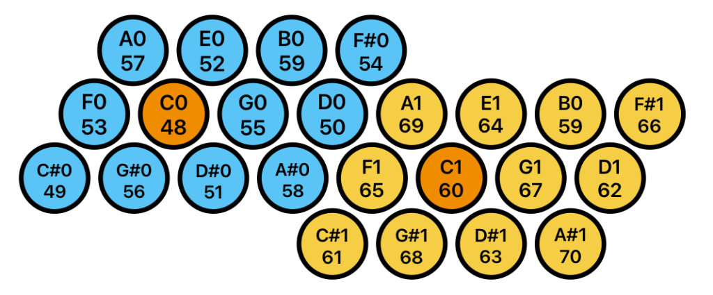
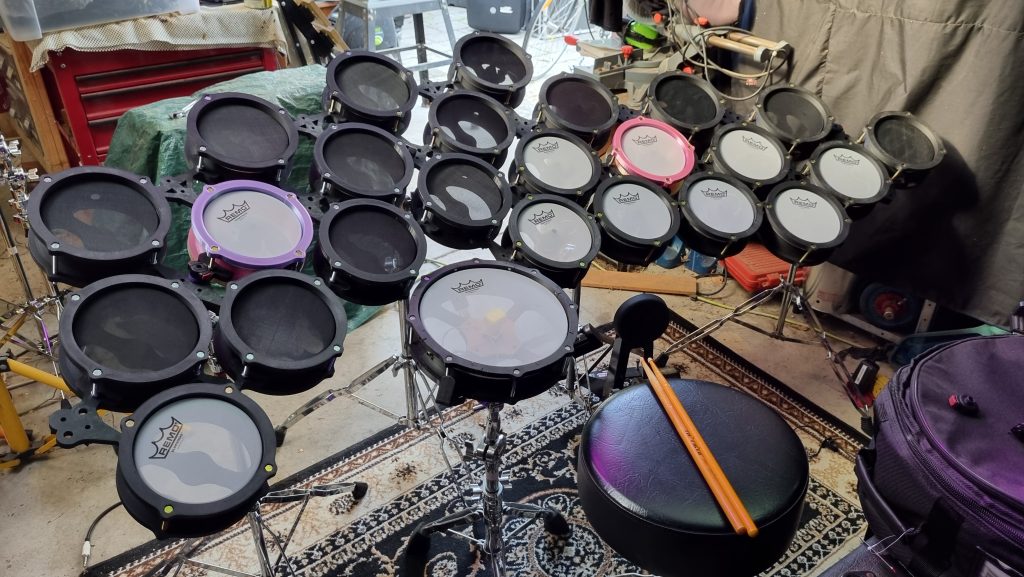
The current form of the e-drum array is two adjacent octave groups, requiring 4 rows of drums. The array has a pronounced curve around the performer, requiring each row of drums to have increased space between units.


Four rows of drums require 3 different clamp styles (A, B, and C, shown on the left) to accommodate the expanding width between the drums. In order to make the array neater and more stable, we can also remove unused mount points at the edges of the array to make edge clamps, such as the clamps D, E and J. After assembling the array full array for the first time I felt that the top row of drums in each octave needed more support (they were held at only one point) so I created fill-in clamps H and I to add rigidity.
The clamp set
| Row 1 | 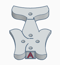 |  |  |
| Row 2 | 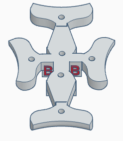 |  |  |
| Row 3 | 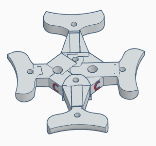 |  |  |
| Row 4 |  |
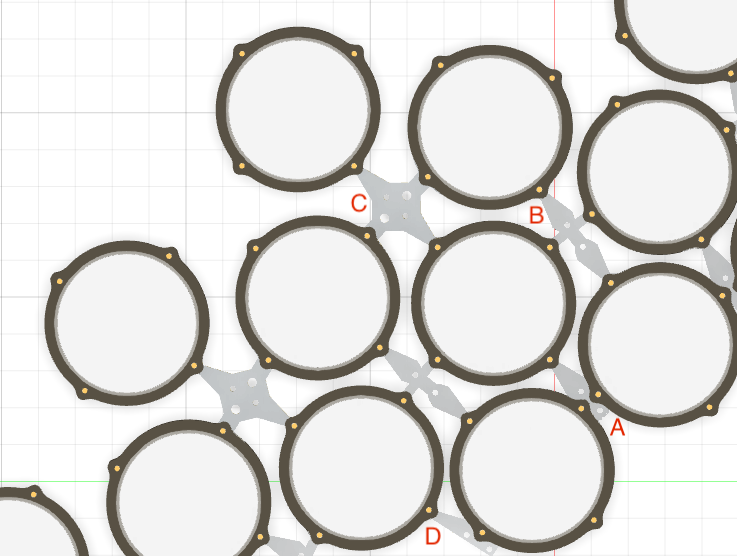
Assembly Plan

Each of the clamp models available on this site has an identification letter somewhere on the part that relates to the assembly diagram above. To assemble the full 24 drum array you will need: 3 A clamps, 4 B clamps, 4 C clamps, 1 D clamp, 1 E clamp, 3 F clamps, 1 G clamp and 1 j clamp.
Putting the Drums Together
When the array begins to take shape it can become difficult to access all of the clamps and nuts, so these instructions are intended to be very general and simply illustrate the required steps. You will need to find your own strategies to complete the whole array.
- Prepare the rim
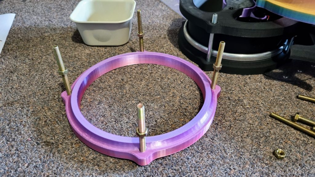
Push the 75mm M6 bolts through the rim, ensuring that the hex heads are embedded in the matching rim sockets. Refer to the layout map above and put a nut on every bolt that will need to carry a clamp. This is my ‘C1’ drum, so every side is attached to another drum.
Inset the mesh skin and place the clamps over the top of the nuts.

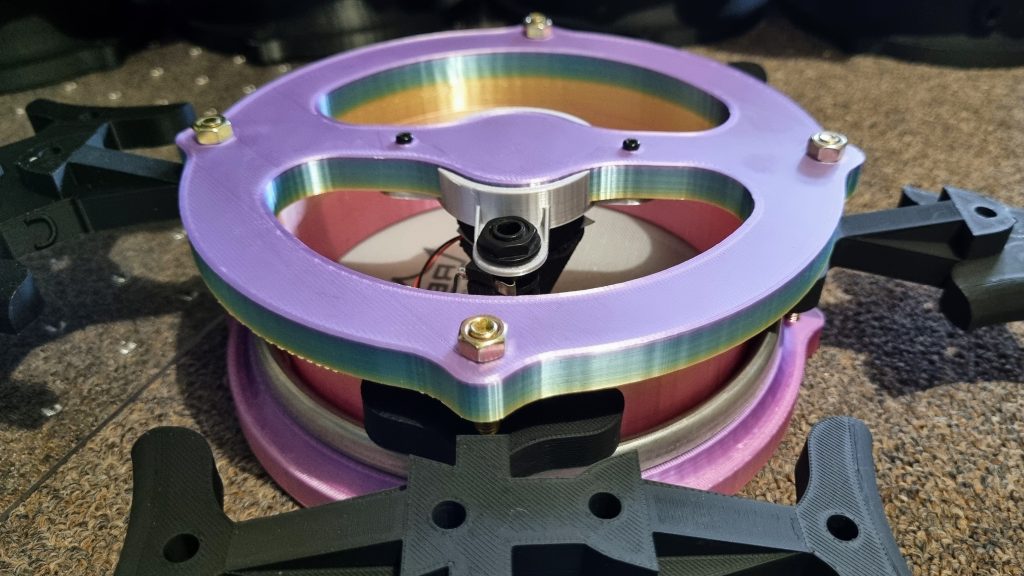
Insert the shell and fit nuts to all of the bolts. Mesh skins do not require a lot of tension – it is possible at this stage to reach playing tension by compressing the rim and shell with your hand while tightening each nut. The drum trigger is shown mounted in this photo, but they can be slipped into place though the bottom of the drum after assembly as well. This also allows for easy maintenance of the triggers if any become faulty.
Push the clamps firmly against the bottom rim of the shell and secure them by finger-tightening the loose nuts installed in the first step.
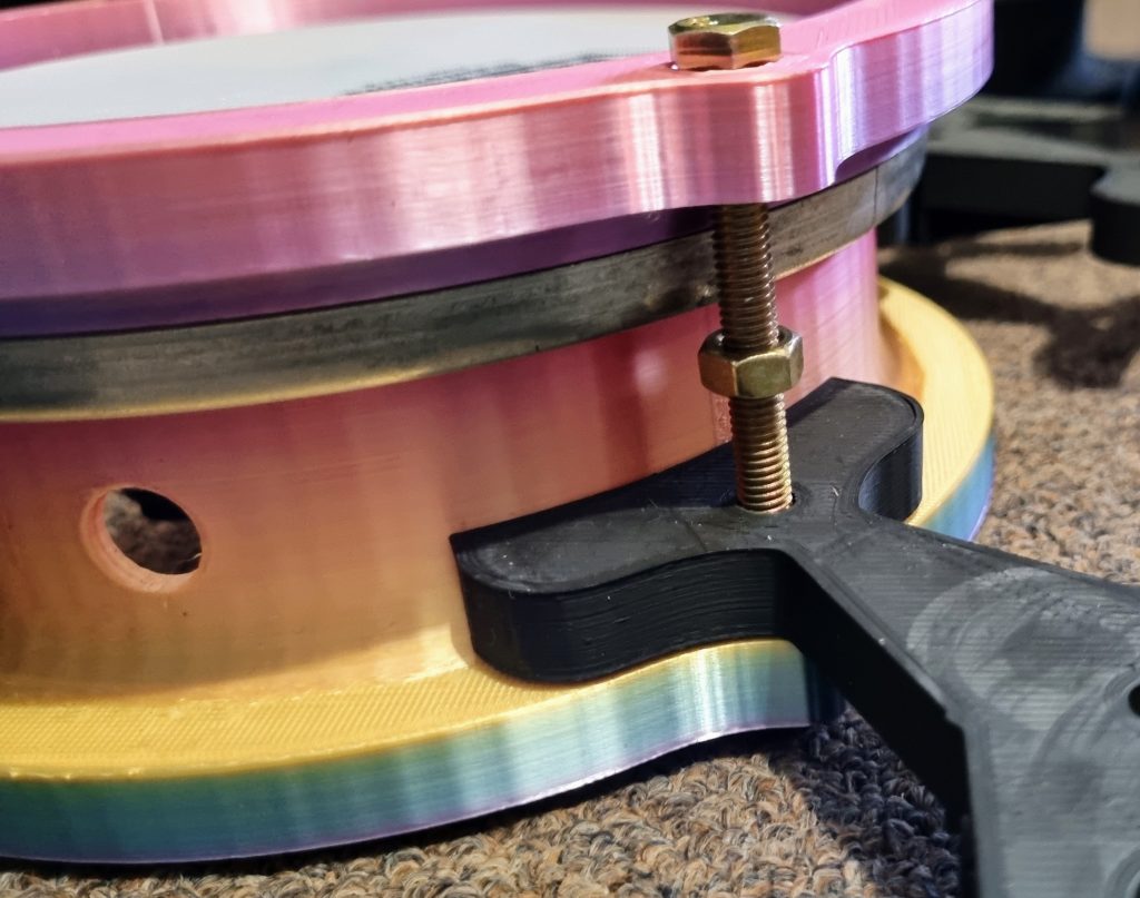
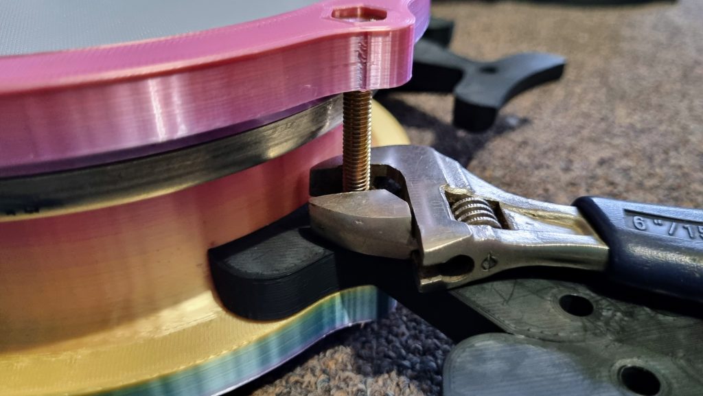
You can now tighten the nut from above the clamp (as shown) or from the other side of the lower rim, which may be easier to reach as the array grows and drums are surrounded by their neighbors. Tightening from below the drum with slightly raise the skin tension on that lug. Mesh heads do not need to be tuned, so small variations like this are not detrimental to the drum performance.
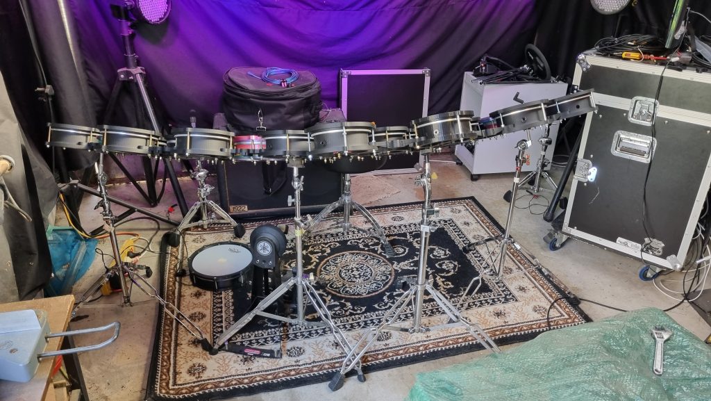
Mounting of the array.
All of the clamps have holes designed to accept the top of a small cymbal stand. The setup below uses four cheap stands to support the array, or two to support each octave. This allows the array to be spit into two groups if the whole array is too large. I also prefer to break the array into octaves for storage and transport. You are free to use as many cymbal stands as you wish, but each octave should be independently supported.
Also shown below is a 10″ drum assembled from 3D printed segments.
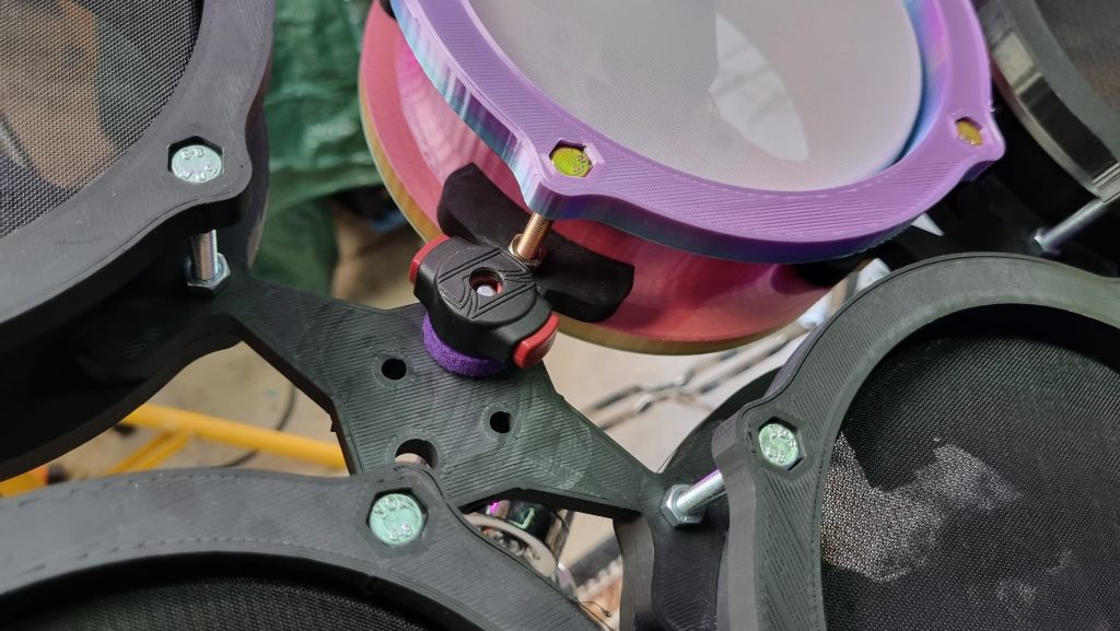
A ‘C’ clamp attached to a cymbal stand. The ‘C’ row has larger holes that fit my Tama cymbal stands. All other brands that I own work with the smaller holes. It is not necessary to use a cymbal topper, the weight of the array is sufficient to prevent it from moving.
Connecting the drums to the controller will be covered in the post detailing the electrical and software design.