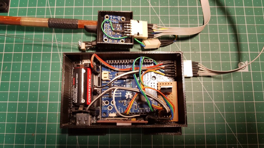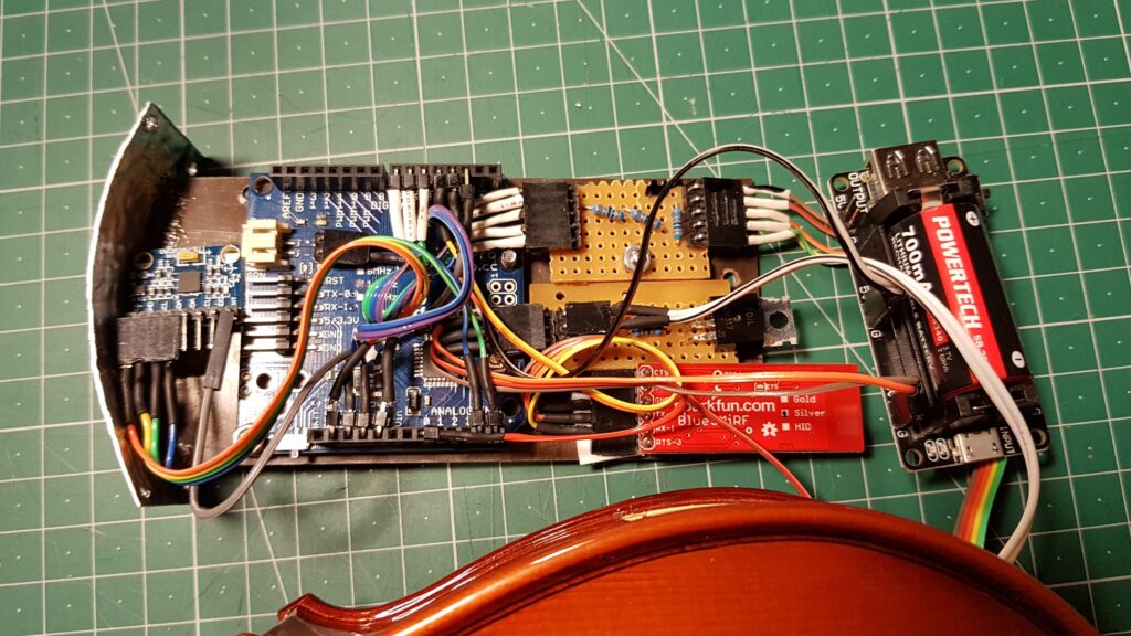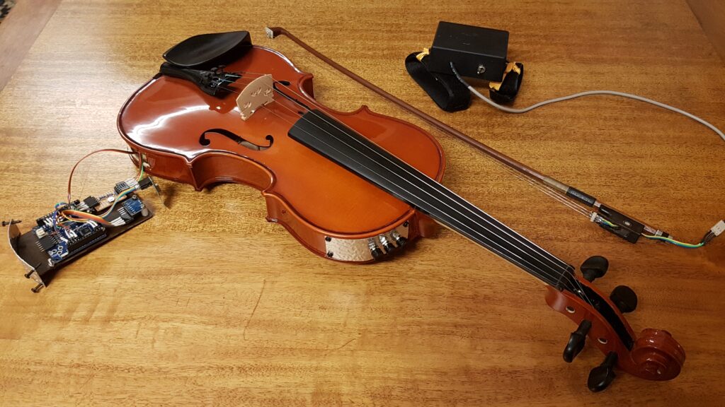
Recently I attempted to create a violin controller that used lengths of nichrome wire to replace the horsehair in the bow. The theory was that I could use the predicable resistance of the nichrome to detect where the bow was contacting a conductive element on the violin bridge. It turned out to be a little more complicated than I anticipated.
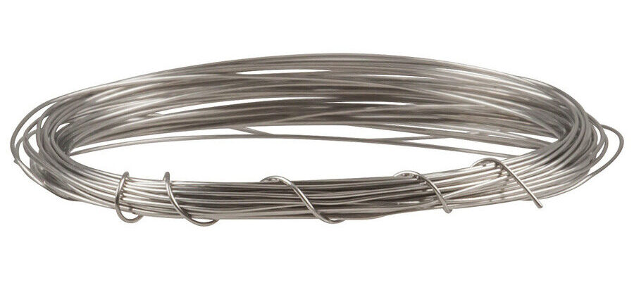
What is nichrome?
Nichrome in an alloy of nickel, chromium and (often) iron. It has high resistivity and is used to construct heating elements. DIY types would know it as the hot wire in a home-made foam cutter. The resistance increases linearly with length – a property I thought would make it ideal for constructing my own sensor.
Turning nicrome into a length sensor
Arduinos, and their clones, make measuring resistances very simple. The usual method is to construct a voltage divider using 5v or 3.3v sourced from the Arduino (or a power supply) and a known resistance (usually something in the order of a few kΩ). There are two reasons why this method will not work with the length of nichrome I am using in my project:
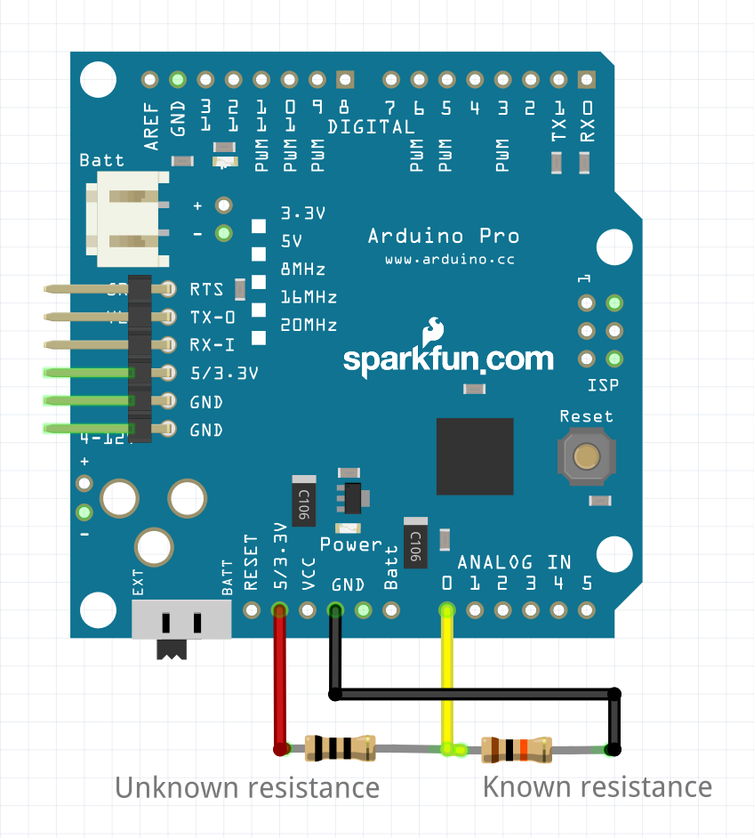
The sensitivity and voltage range of the Arduino
The change in resistance over the length of nichrome I am using is small – only ~16Ω, and I need to measure that small resistance with the highest accuracy I can get.
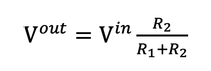
Using the voltage divider equation, a divider using, for example, a 1k resistor as the known value will give me a tiny range of 5V to 4.92V on my 5V powered Arduino Pro.
The standard Arduino only has a 10 bit resolution for measuring that input voltage – that’s a 0 – 1023 range, of which I can use ~80 with that tiny change in voltage. To make matters worse, in the real world you sacrifice some of that range to ensure that the values you are measuring are all relevant and all captured. A system set up to use all of the input range has no room for values to slip, components to change, or for just the random behavior that seems to creep into home-built hardware. It is possible, however, to tell the Arduino to use a different measure for comparing voltages.
Input voltages are usually measured against a reference voltage that matches the voltage used to power the Arduino. This is convenient, as the Arduino is commonly the voltage source for sensing attached switches and potentiometers. It is possible to set a different reference voltage inside the Arduino, using AnalogReference(). This approach has some limitations, not the least of which is the lack of uniformity across the range of Arduinos and clones. This project began on an Arduino Mega clone, was installed on genuine Arduino Pro units for the final product and was moved to a Duinotech Nano for one of the interfaces. The second round of hardware has spent some time installed on 3.3v Duinotech ESP32s and a 3.3v Arduino Nano 33 BLE Sense (the sense has an optional 12 bit resolution but uses 10 bits for compatibility).
Lets’s look at the available reference voltages for the family of boards that I have used for the first round. Setting anaglogReference(INTERNAL) gives different results on different boards, some values are only available on Mega boards and the standard value differs between 5v and 3.3v versions of the same boards.
Arduino AVR style internal reference voltages:
5V (5V power supply) or 3.3V (3.3V power supply)
INTERNAL: 1.1 volts on the ATmega168 or ATmega328P and 2.56 volts on the ATmega32U4 and ATmega8 (not available on the Arduino Mega)
INTERNAL1V1: a built-in 1.1V reference (Arduino Mega only)
INTERNAL2V56: a built-in 2.56V reference (Arduino Mega only)
So why not maximise the voltage available for measurement by using a known resistance similar in value to my length of nichrome? Because that would be very dangerous for my Arduino. The nichrome in the bow forms a loop when the two strands are bridged by a metal contact, so the total resistance would be < ~14Ω when in use (you won’t usually use the very ends of the bow, so you won’t see the full 16Ω). Even if we double that and use a 25Ω resistor, with a 5v source that is is ~200mA (1W @ 5v!). I’ve looked through the specifications for a few models of Arduino, and they have all had a 40mA maximum for IO pins. So how do we do it safely?
Safe sensing
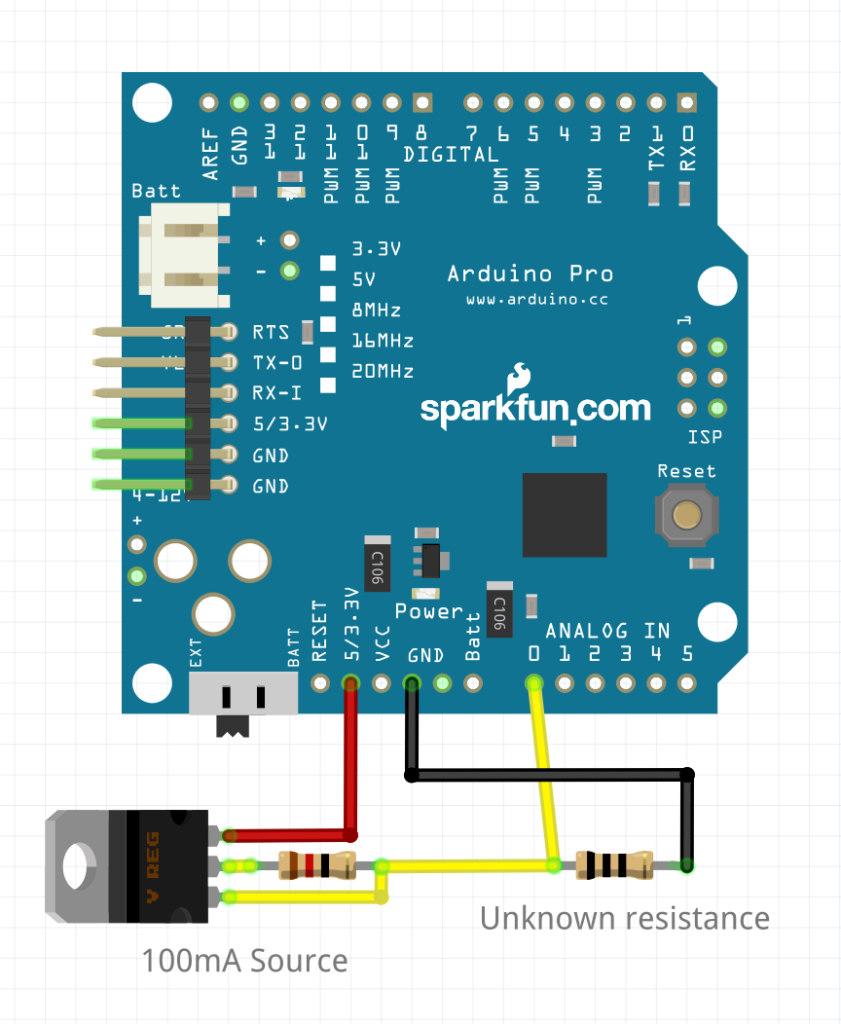
We can measure low resistances safely using an external constant current source. R = V / I, so with a known voltage and current we can measure resistance without presenting a risk to the Arduino. The LM317 regulator shown in the diagram provides a known 104mA. We can round this down to 100mA (0.01A) and see that R = 10V. My 14Ω usable resistance range is now a manageable voltage range of 0 – 1.4V of 1.6V total range measured against 5V. That immediately improves the 5V Arduinos measurement resolution to ~287 of ~328. The hardware will be re re-implemented on newer 3.3V modules which improves the Arduinos performance to ~434 of ~496. The 3.3V Nano 33 BLE SENSE has an optional 12 bit mode (0 – 4095) that improves the bow reading accuracy again to ~1736 of ~1984.
Making it Better
There are some easy ways to make the hardware better – the most obvious being altering the current source, but these modules are already built and I’d like them to be useful for other low resistance tasks, so they’ll stay at 100mA for now. There is, however, a simple way of drastically improving the apparent resolution of a hardware sampling system without touching the hardware at all:
Next installment: oversampling
LM317 modules in action:

