Posted on

DIY 26 Speaker Ambisonic Dome – Part 5

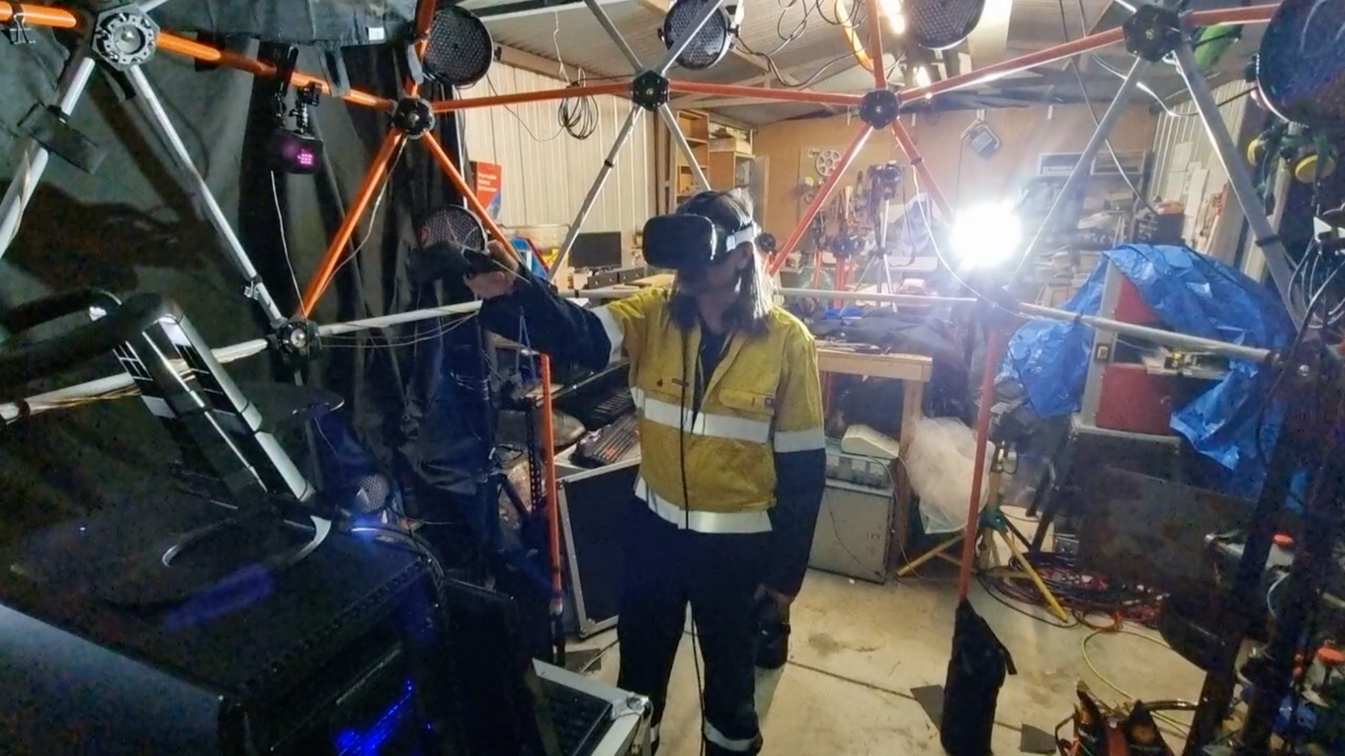
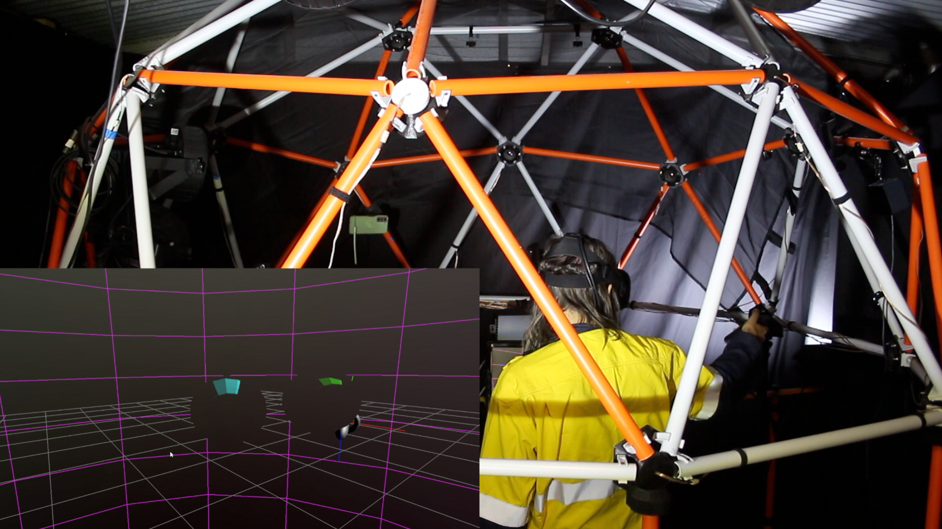
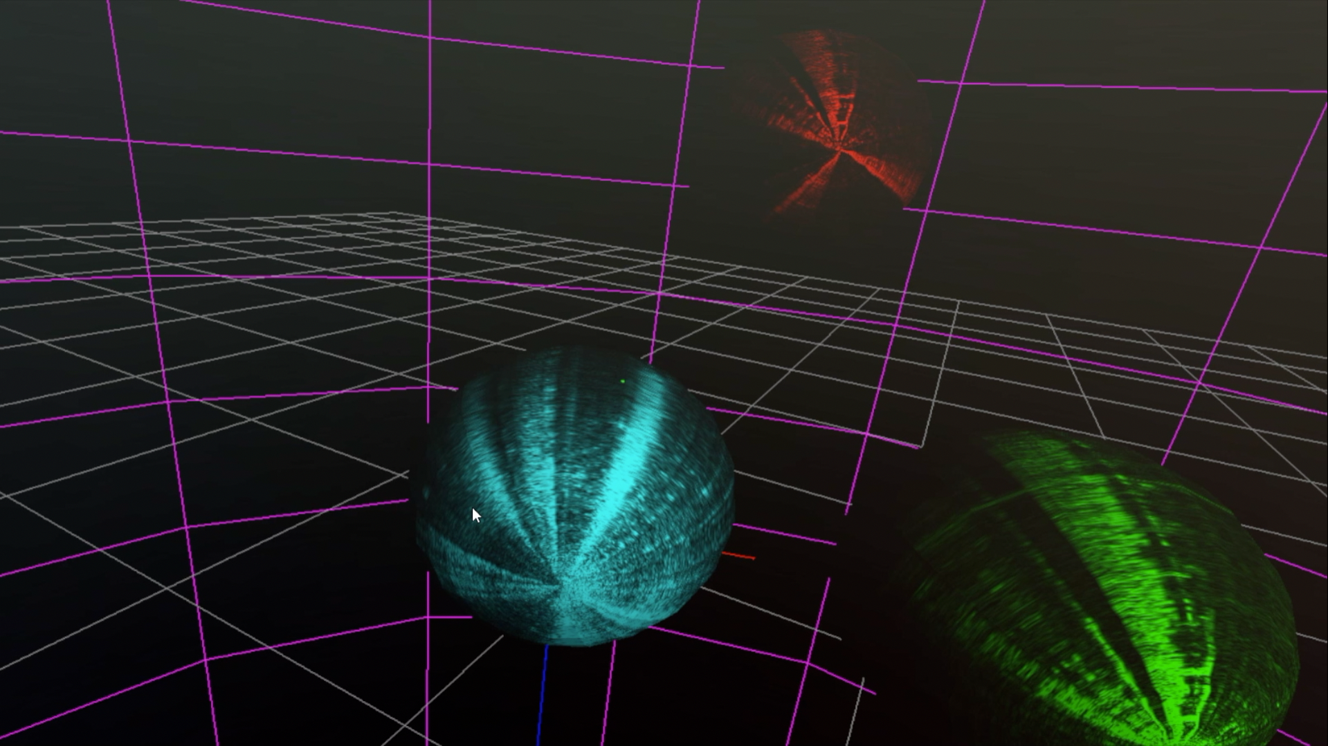
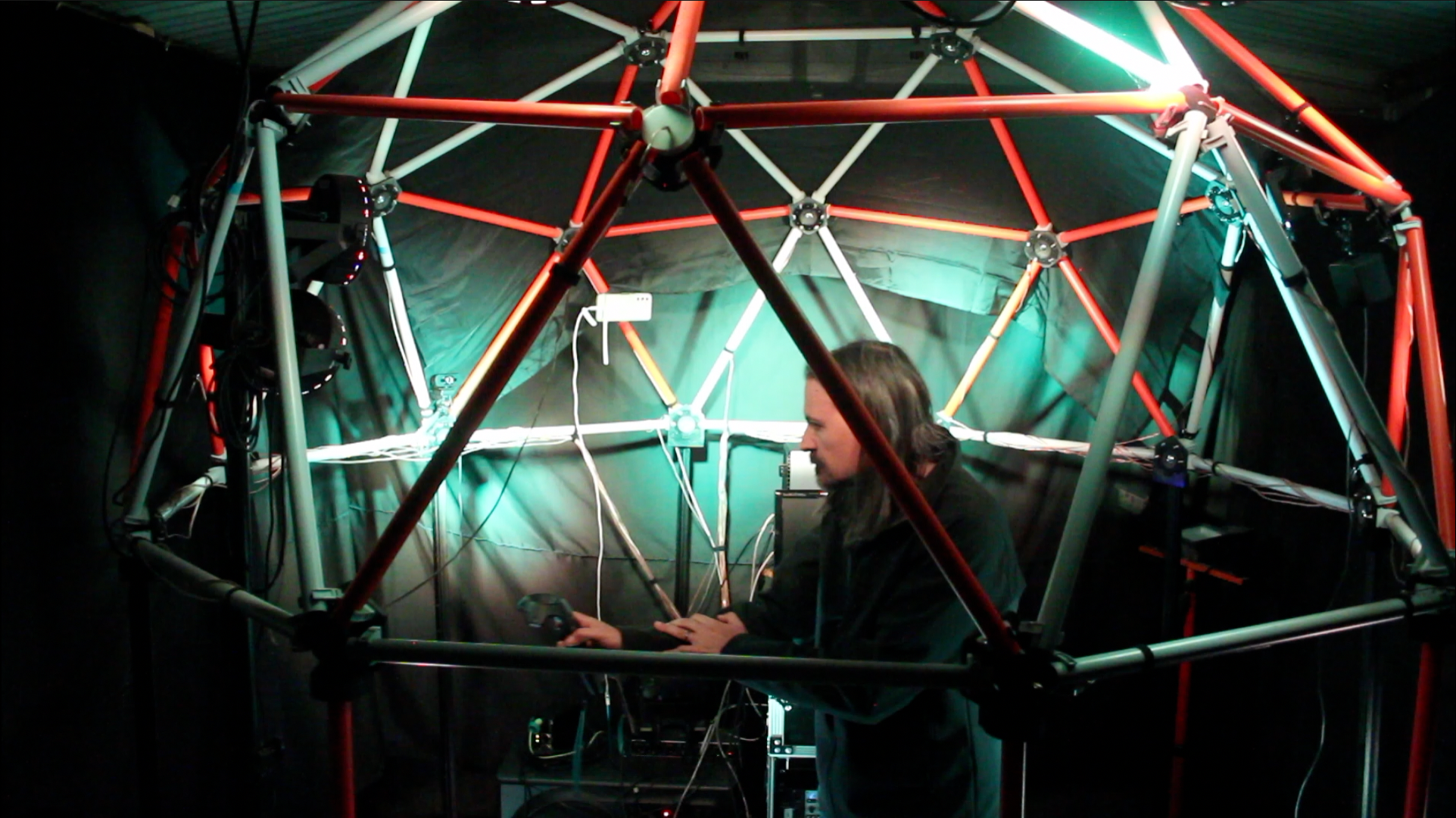
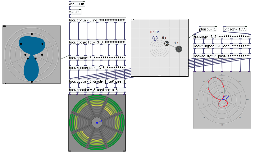
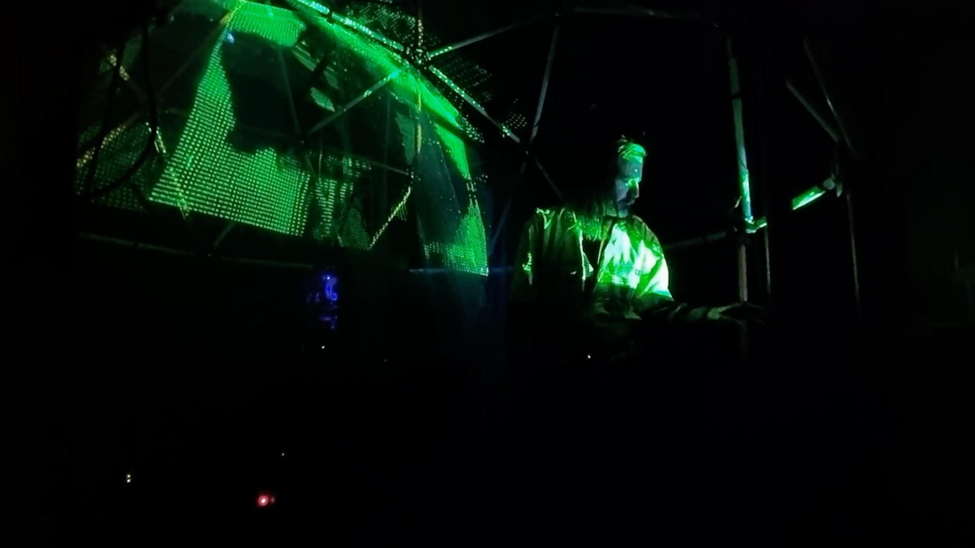
This small Ambisonic dome is, by design, a one-person experience. These works combine the immersion of Ambisonic audio with interactive augmented and virtual reality, creating very personal worlds that cannot be experienced through 2 dimensional media. Each work gives the audient different levels of agency, discovery and immersion. The VR headset views and projections are all generated in real-time with MAX. The audio content is a combination of Ambisonic processing in MAX, Cherry Voltage modular synthesiser and Native Instruments Reaktor.

These pieces were made to be experienced, not watched. Watching an immersive experience from the outside is like eating the menu at a restaurant – but below is a collection of short clips showing the system in action. ‘Coil’ and ‘Living Room’ use the Vive controller as an exploratory tool.

‘Coil’ places you inside a gradually intensifying map of the electromagnetic radiation emitted from consumer devices in a kitchen & lounge room. Discovering the unseen topology of the fields we live with every day is surprisingly visceral.

‘Living Room’ scales Australia down to 3 meters inside the dome. Dynamic maps of bushfire, rainfall and temperature variation can be selected via a bluetooth footswitch. Although you are inside the data projection, an FM modular synthesiser controlled by the position of the Vive handset is your only feedback, growing more discordant as time passes and the maps intensify. Areas without change are the only respite but they grow fewer and smaller as change accelerates.

‘Workspace’ is a subset of tools designed to make a complete VR mixing environment. The spherical audio emitters can be placed in 3 dimensional space, adjusted for volume and given animation paths that they will repeat until reset. Evaluating the efficacy of my DIY Ambisonic dome when combined with immersive headset VR in this manner was the subject of my thesis.

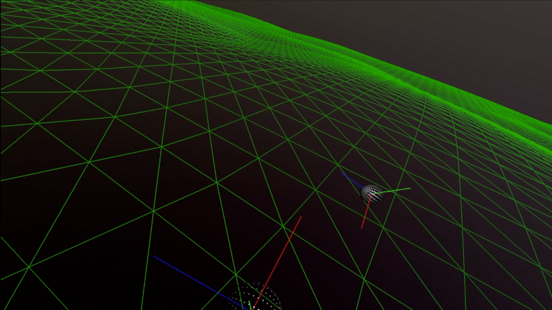
‘Drown’ is simple, largely passive and surprised me with the nasty intensity of the conveyed experience. This work is entirely dependent on the power of visual and audio VR immersion. Seated in the centre of the dome, over several meditative minutes your mind accepts the reality of the undulating wireframe ocean and drifting sound emitters. Then you realise that the level is rising. The moments when the water surface is just at head height and the waves are higher than you can crane your neck are genuinely disturbing.

A slightly redacted version of the artist statement can be downloaded here.

Posted on

DIY 26 Speaker Ambisonic Dome – Part 3

Software

Back in the 70’s you could buy hardware Ambsonic decoders, such as the Integrex. They were niche, and usually available as a kit you built yourself. Reportedly, they did not perform very well though I’d love the opportunity to hear one to judge for myself. The largest drawback of a hardware solution is that you are tied down to one configuration of speakers. Personal computers have become so inexpensive and powerful that it is easier and far more flexible to drive the dome from a software solution.

The ideal software for cost effectiveness is Pure Data, also known as PD. It’s hard to beat free software for price. This is an open-source solution and comes with all of the benefits and drawbacks of an open product. There is a lot of support and a real community around PD, but if it breaks, you get to keep both pieces and there may be no-one interested enough to help you. This is also a good way to describe the current state of Ambisonics in PD, specifically the HOA toolset.

HOA tools from the PD patch repository.

It looks great – it also doesn’t work anymore with the current version of PD and hasn’t worked for years. You could try running it in a version of PD from when it was released, but then you will discover that other parts of PD will not work because they are too old. To borrow a phrase from the Linux community, you are now in ‘dependency hell’ where there is no combination of software versions that will work for everything you want to do.

I’ve run into this problem a lot when developing for Arduino, where it is particularly bad. I often wonder if anyone in the Arduino community actually gets any real-world work done with the products they write about on their webpages. A popular library for processing the output of gyroscopes has an axis completely reversed for some hardware. None of the popular Youtube channels or blogs even noticed and the main library remains unfixed.

With PD reluctantly excluded, we must turn to MAX/MSP and MAX for Live. The HOA tools from PD are also available in MAX, but why make life difficult when the excellent ICST Ambisonics package is available for free in the package manager.

ICST Ambisonics in MAX/MSP

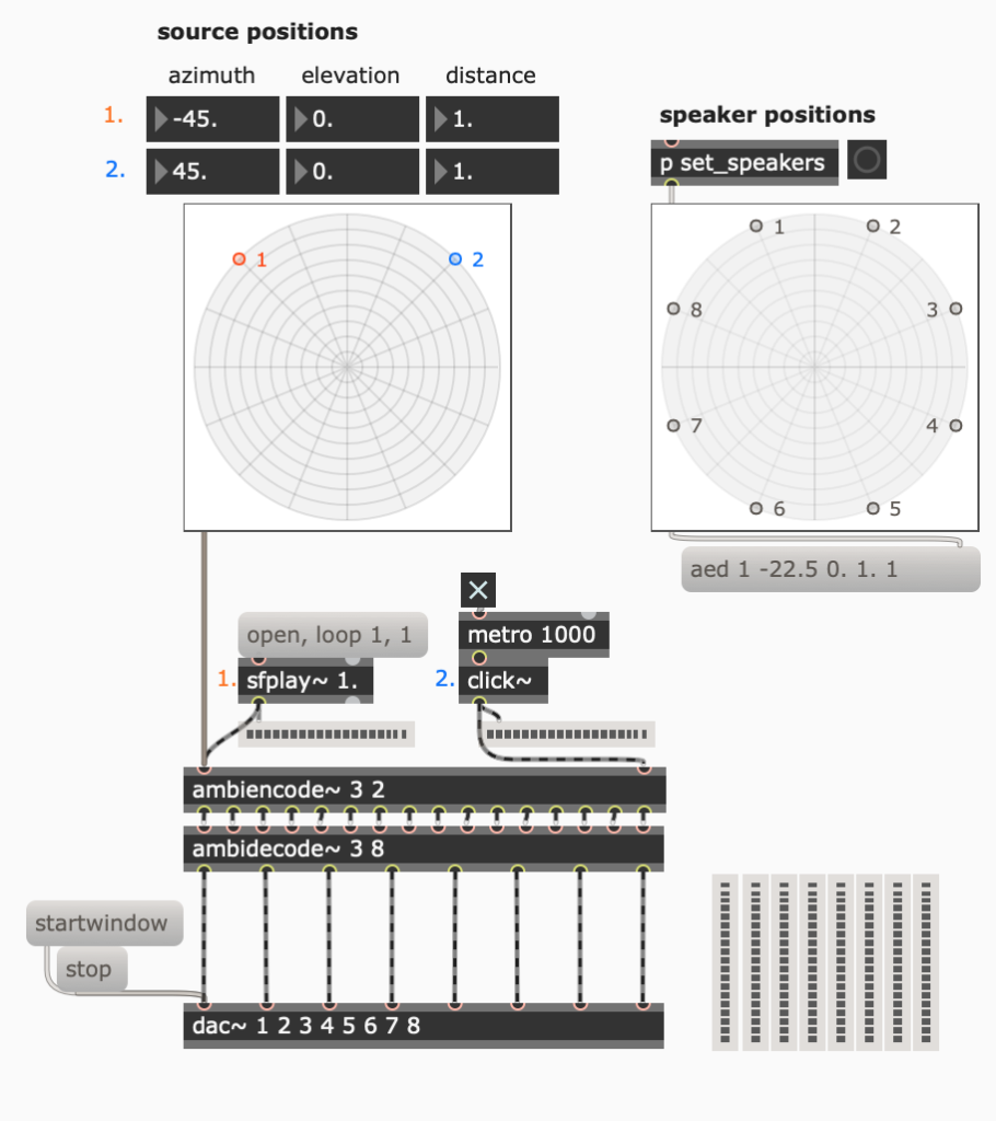
ICST Ambisonics makes a complex job easy. If you know where your speakers are and you know where your sources should be (or you have audio already recorded in a surround format), you can have audio coming out of the array in just a few minutes. My own software stores lists of speaker configurations to suit different rooms. You can select 4, 5, 10, 20, or 25 channels (plus the subs channel).

A simple decoder for playing prerecorded sound through the dome. The speaker array selector buttons are on the right.
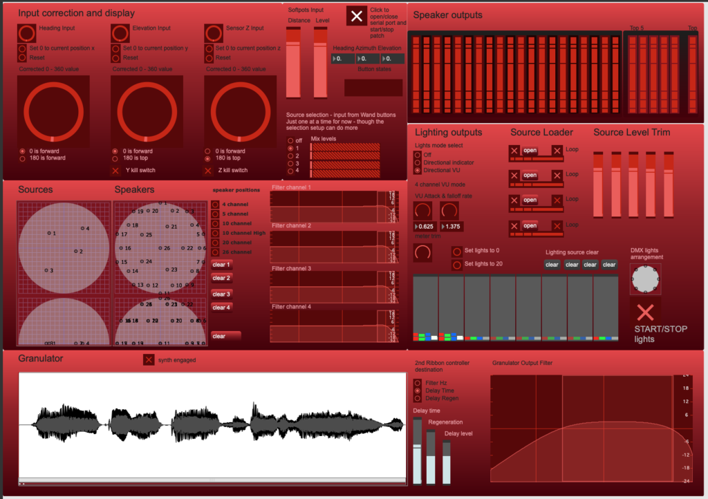
My own MAX patch for an Ambisonic mixer/instrument and DMX lighting controller
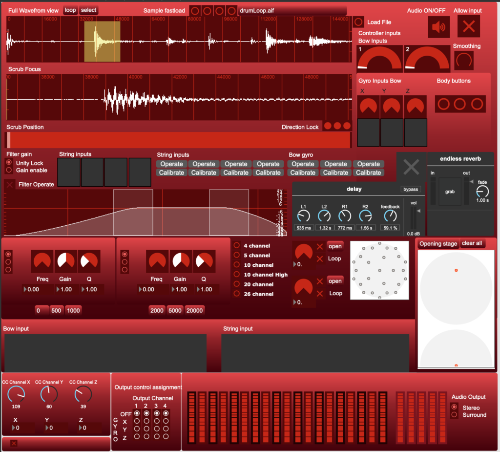
This one is an interface for an Ambisonic computerised version of Laurie Anderson’s tape bow.
The Ambisonic decoder plugs right into the outputs from your computer. Two FireWire Focusrite Liquid 56s are twin-linked together to create this output set. It all fits within the bandwidth of one single FireWire 400 connection.

Unfortunately, MAX/MSP is not an open source product and it is not cheap. I still hope to replace MAX with PD when I have enough time to return to programming for fun, but that time may be never.

Waves NX

Although the dome is portable, transporting it requires several large boxes and about 6 hours of swearing to set it up (if you are on your own). There are some clever tools available to bring something approaching surround sound to your headphones.

Let’s first talk about mix room simulation.

Room simulation tools have been around for a long time. I used to use Focusrite’s VRM (Virtual Room Modelling) until an Apple OSX update made it inoperable. These tools were very polarizing when they were released, many engineers hated they way they sounded. One friend who disliked the effect flipped through the presets, turned it off and on a few times, complaining about how fake and smeared the sound was. If you have the desire to try one of these tools, this is exactly how not to audition one. By turning it off and on and jumping from one room model to another you are concentrating on the differences between the emulation and the reality – you are creating a condition where the emulation cannot win.

At first, I didn’t like the VRM much either, but I left the headphones on and set to work mixing. About fifteen minutes later there was a knock at the studio door and I leapt to the room controls to turn the monitors down. I had been fooled and completely forgot that I wasn’t listening to speakers. The same approach works with Waves NX – don’t dismiss this technology before giving it a fair listen.

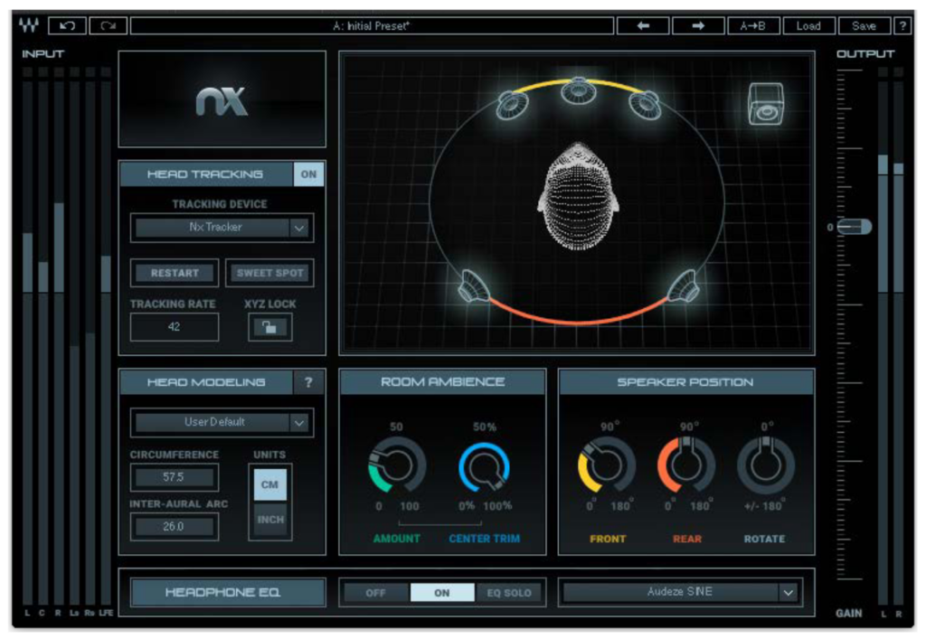
Waves NX is step above a static room emulator. It is capable of tracking the movement of your head, either through your laptop’s camera or by using a special bluetooth sender that attaches to the band of your headphones. Some popular headphones have frequency compensation curves built into the plugin. Measure the circumference of you head and the distance between your ears around the back of your head (the inter-aural arc) and Waves NX will use a HRTF (head related transfer function) to calculate what each ear should be hearing as you move your head.

The Waves NX interface. Note the area for entering your head measurements in the lower left.

Waves NX is not kind to your processor if you use webcam tracking, and the positional lag as the camera system chases your face wrecks the effect a little (in a similar way to visual lag ruining your Virtual Reality immersion). It does work though, and a slew of competitors are releasing similar products.

DIY 26 Speaker Ambisonic Dome – Part 1, The Dome Structure

DIY 26 Speaker Ambisonic Dome – Part 2, The Audio

Posted on

DIY 26 Speaker Ambisonic Dome – Part 2

The audio

My vision for this project was to create an ambisonic dome for tinkerers and musicians who have a tiny budget but don’t mind putting in some DIY time. One of the biggest hurdles for keeping the dome design affordable was working out how the audio amplifiers and computer interfaces could be made or found cheaply.

Amplifiers can be very cheap when you need one or two channels – any Hi-Fi amplifier will do. If you want up to 6 channels you might be able to re-purpose an old surround-sound amplifier. You can’t get 26 channels of ready-made audio cheaply. Commercial power amps that handle over 16 channels are thousands of dollars. It was obvious that I would have to make something myself.

Digital amplifiers

I have been impressed by some of the small digital amplifiers available through Ali Express and Ebay. They can run from a huge range of voltages, deliver lots of power and are typically quite compact.

This is a Nobsound Mini Bluetooth Power Amplifier. You can find comparable models for ~$40-60. Audio performance is very good, but It is best to avoid the cheap Bluetooth implementation in these budget devices.

$20 per channel is still far too expensive for powering the dome – I’ll need 26 channels of audio. You can, if you look a bit harder, find digital power amplifiers sold in a very basic form, just a PCB and few support components. I found the PAM8610 stereo amplifier for $3.45

Digital amplifiers are very, very efficient and can operate without heatsinks for low power loads. The speakers in my dome are very small, but there are a lot of them. Sounds, even very directional ones, are represented in the dome by an array of speakers sharing the load, keeping the power demand on each speaker small. These little modules seemed perfect and my first test module seemed to perform OK. I ordered a whole pile of them and started on an enclosure.

The digital power amp. Each little module is two channels.

For each stereo module I 3D printed a mounting ‘sled’. The sled had push-fit fingers that held the modules in place, wire routing holes and mounting holes that could take an M3 bolt or a small cable-tie. It went together very quickly, looked neat and could be powered from a single 12V laptop power supply. It was also unusable.

I had noticed a small amount of noise during my individual module tests but I was entirely unprepared for the wall of noise that 26 channels of the PAM8610 would put out. It wasn’t only hiss – these units were interfering with each other, causing some very harsh noise components. I leveraged my years of experience fighting feedback squeal in valve amplifier designs and re-routed the grounds and power supply lines with a star-topology. A small improvement. I bypassed the power supply on each board with an MKT capacitor and added filtering at the power entry. Another small improvement but not enough. I had a week left before I had to exhibit the dome and I still did not have a working amplifier, so I needed to change course and try something different.

Old fashioned linear amplifiers are also available in chip form – though they can be annoying to work with at medium power, needing heatsinks or direct mounting on a metal case to keep them from destroying themselves through waste heat. I didn’t have time for all that, but I remembered that Jaycar stocked pre-made encapsulated amplifier modules. I bought every one they had and bulk ordered more than they probably would have sold in a year.

Not nearly as visually satisfying, but it did they job for the exhibition night. These amplifiers are now housed more neatly in a roomy 3U high case.

The amplifiers were sorted, but I still had to route sound to the dome from my computer. This is another area where a small number of channels is very inexpensive – stereo and even 5.1 surround sound is often built into motherboards or available on a cheap USB dongle. Finding 16 channels will probably cost you ~$2000, and 32 channels ~$4000. Although I would love to be able to justify buying an Orion 32+ from Antelope Audio, that would be overkill for this project. I also don’t have $4000 to spend for fun.

Whatever happened to FireWire?

FireWire equipment is available at bargain prices, if you are willing to take a risk on second-hand gear. FireWire used to be the only connectivity choice for professionals – unless you had some kind of solution that came with its own PCI card and bespoke connectors. USB was too unstable, too slow and had an air of “Intel PC” about it when everyone was using Apple to get creative work done. Then everything changed. Windows became stable (or stable enough depending on your luck and hardware) and Apple forgot that their professional users even existed, abandoning the Mac Pro and removing ports and functionality from their Pro laptops. It became nearly impossible to guess if your expensive interface would survive Apple’s next operating system upgrade. I have a graveyard of interfaces that no longer work with Apple computers – Focusrite, Digi, Edirol, Steinberg, Tascam, IK and others that I have forgotten about that now reside in dusty boxes in the shed.

There are a lot of FIreWire interfaces out there that are still compatible with current operating systems and doing good work but Firewire is obsolete technology and the prices really reflect that. You can buy large capacity systems cheaply but you have to be very careful what hardware you buy. Your hardware choices may restrict you to a few compatible versions of your operating system, preventing you from upgrading until you sell it. The interfaces I am using now are compatible with MacOS 12 but will probably not work for much longer.

Focusrite Liquid Saffire 56. You’re not supposed to be able to link them together – but you can.

I already owned a Focusrite Liquid Saffire 56 with a pair of additional 8-channel optical inputs. It was a great inexpensive system for recording live bands. I was able to find a second 56 for ~$600. Focusrite FIrewire interfaces have a special mode called ‘Twin Linking’ where the driver software ties two interfaces together as one unit. The documentation says that you can NOT link two 56s together – but you can. This configuration is not allowed by Focusrite because, with every input and output channel running, it is possible to exceed the maximum bandwidth of the Firewire 400 connection. Fair enough – but they don’t stop you from just doing it anyway. My only concern is to push 26 channels of audio out of the computer to run my dome and they are able to handle it brilliantly for a fraction of the price of a 32 channel interface.

Since writing this entry I have changed the hardware setup several times. I discovered a cheaper hardware combination that pairs two old Alesis ADAT recorders with the Liquid Saffire 56. ADAT units are currently $100 or less each. The drawback of using the first generation black case ADATs is a fixed -10dB output from the converters, which has to be matched to the +4dB outputs of the Saffire. I modified the dome software to store presets for individual channel gain and the problem was fixed. Later ADAT units (with silver cases) can output at +4dB.

Alesis ADAT recorders in the dome controller box. These are a very cheap option for adding channels to an audio interface.

In the interests of maintaining compatibility with modern operating systems into the future I am transitioning the dome to combination of an RME Fireface 800 and two Behringer ADA8200 ADAT converters. RME have an excellent record of keeping every one of their interface drivers up to date. Their very first Firewire interface is still supported. The ungainly chain of dongles required to attach it to my M1 Mac Mini (Thunderbolt 3 to Thunderbolt 2 to Firewire 800) is rock solid in daily use. Eventually I will probably abandon Firewire and move to the RME Digiface USB. This tiny interface is just a box of ADAT lightpipe ports, allowing me to connect four ADA8200 units for 32 output channels.

DIY 26 Speaker Ambisonic Dome – Part 1, The Dome Structure

DIY 26 Speaker Ambisonic Dome – Part 3, The Software

Posted on

DIY 26 Speaker Ambisonic Dome – Part 1

This project seemed fairly simple when I started designing it around March 2020. 26 Speakers, 26 amplifiers, an ambisonic decoder and some simple arduino based controllers. It got out of hand very quickly and although I am happy with how the project has come together, I have spent more time than I would like to admit wanting to set the whole thing on fire and forgetting that I ever wanted this thing to exist.

The Dome Structure

It’s what everyone sees first – it defines the whole project. It turned out to be the easiest part.

The first test assembly, proving the viability of the electrical conduit and PLA printed hubs

The hubs are 3D printed from PLA using a very cheap little 3D printer from Cocoon Products. It’s branded ‘Balco’ and I think that this model was once sold through Aldi. Although it was cheap it has some features that I think a 3D printer must have in order to be genuinely useful.

  • A heated bed – if you print in ABS or other less forgiving mediums than PLA you will need a heated bed. Without one your prints will curl up from contraction of the hot plastic while the job is still being printed. Sometimes it still will anyway. Ambient temperature can have a big effect on the quality of your prints. On cold nights I’ve built boxes from styrofoam, cardboard and clear polycarbonate around to printer to keep the heat from the bed escaping. A ready-made fully enclosed printer would be great, but is three times more expensive than my Balco.
  • Standalone operation from an SD Card – I have CNC mills that are driven straight from the computer (via the parallel port). It’s great to have a cool animated display (from Linux CNC), but it requires me to have a monitor, computer, keyboard and mouse for each mill. Either that or have my laptop tied up for four hours during a cut. It’s great to just load a GCode file onto the SD Card, open it from the touch screen and walk away.
  • Moving bed gantry design – this is nice because the bed doesn’t move beyond the boundaries of the printer base. For messy people like me, this means that your printer won’t push things off the bench. (My CNC mills will do this all the time if I’m careless).
  • A cool little touch screen with utility functions built in – filament exchange, homing and bed-leveling are all built into the unit. This saves a lot of time and fiddling around.

Files are prepared for the 3D printer using the free software package ‘Ultimaker Cura‘. It won’t help you with modifying your designs, though it can expand or shrink the size – a function I’ve used in very small increments to make the caps fit better on my hubs.

The Dome Components

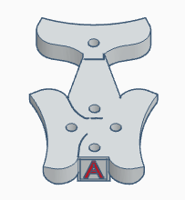
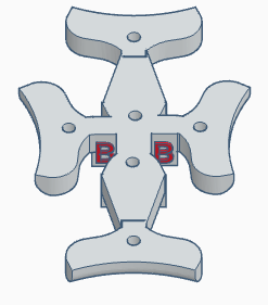
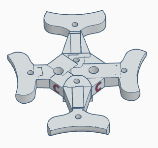
The dome is a 2V geodesic semi-dome, needing three hub types to complete. The clips are electrical conduit clips. Also shown in the picture are the 6cm speakers and the first version of the class D 26 channel power amp. There’s 100m of speaker lead on that top reel – it wasn’t nearly enough.

My original plans were to test print the dome using PLA (it’s faster and more forgiving to print) and, after verifying the design, to reprint the whole thing in ABS for better strength. I never had to. The dome has been set up several times in differing locations, been left out in a thunderstorm, and has undergone rapid unplanned disassembly several times (the first few times we tried to raise a finished dome onto its legs. I’ve had to re-print parts due to breakage only four five six times so far).

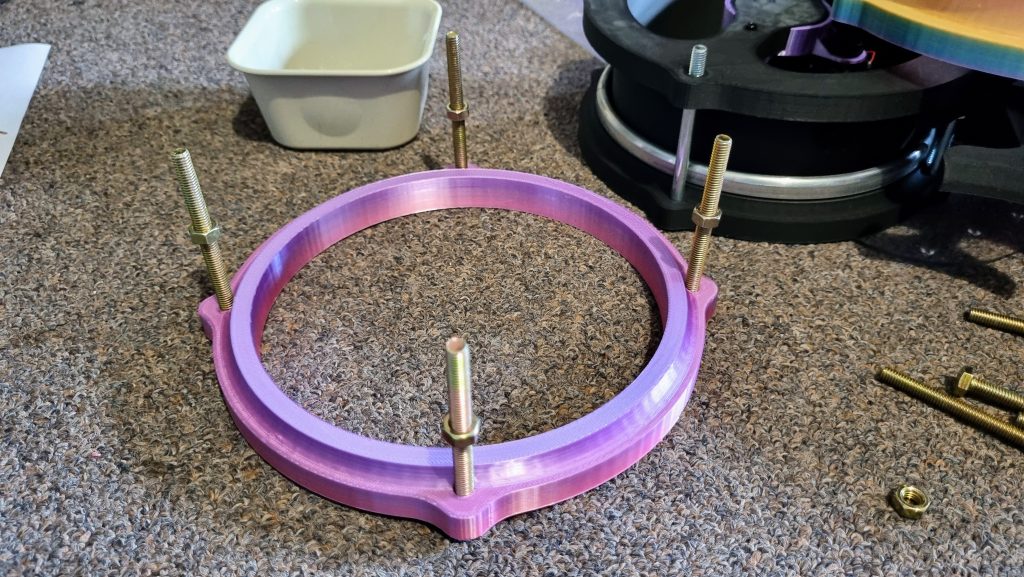
Each hub contains a single 6cm speaker held in place with a printed ring. They are quite small and don’t have a lot of power behind them, so they can’t handle low frequencies. Low frequencies are not very important for directional audio, so a single subs unit can handle the low frequency audio.

Structural test installation of the dome with temporary legs. The ring of computer controlled lights around the base give the performer information about the intensity and position of active voices, controlled by the wireless, Arduino powered gyro violin. The steel picket legs can be reversed and driven into the ground for a sturdy outdoor setup.
Audio rig test with 10 of the 26 channels active. The MAX/MSP powered control software is visible on the laptop screen.

DIY 26 Speaker Ambisonic Dome – Part 2, The Audio

DIY 26 Speaker Ambisonic Dome – Part 3, The Software

Posted on

Nichrome wire as a controller input for Max Msp

The bow hair has been replaced with strands of nichrome wire. When the wires are connected by contact with a violin string or another piece of metal they form a conductive loop. The aim is to reliably measure the length of that loop and deduce the position of the bow. The electronics packages also contain gyros and bluetooth modules.

Recently I attempted to create a violin controller that used lengths of nichrome wire to replace the horsehair in the bow. The theory was that I could use the predicable resistance of the nichrome to detect where the bow was contacting a conductive element on the violin bridge. It turned out to be a little more complicated than I anticipated.

28 gauge (0.3mm) nichrome wire (Jaycar). 13.77 Ω/m resistance.

What is nichrome?

Nichrome in an alloy of nickel, chromium and (often) iron. It has high resistivity and is used to construct heating elements. DIY types would know it as the hot wire in a home-made foam cutter. The resistance increases linearly with length – a property I thought would make it ideal for constructing my own sensor.

Turning nicrome into a length sensor

Arduinos, and their clones, make measuring resistances very simple. The usual method is to construct a voltage divider using 5v or 3.3v sourced from the Arduino (or a power supply) and a known resistance (usually something in the order of a few kΩ). There are two reasons why this method will not work with the length of nichrome I am using in my project:

The usual way to measure a resistance with an Arduino. Ideally, the known and unknown resistances need to be similar, but that is not possible with my project due to current concerns.

The sensitivity and voltage range of the Arduino

The change in resistance over the length of nichrome I am using is small – only ~16Ω, and I need to measure that small resistance with the highest accuracy I can get.

Using the voltage divider equation, a divider using, for example, a 1k resistor as the known value will give me a tiny range of 5V to 4.92V on my 5V powered Arduino Pro.

The standard Arduino only has a 10 bit resolution for measuring that input voltage – that’s a 0 – 1023 range, of which I can use ~80 with that tiny change in voltage. To make matters worse, in the real world you sacrifice some of that range to ensure that the values you are measuring are all relevant and all captured. A system set up to use all of the input range has no room for values to slip, components to change, or for just the random behavior that seems to creep into home-built hardware. It is possible, however, to tell the Arduino to use a different measure for comparing voltages.

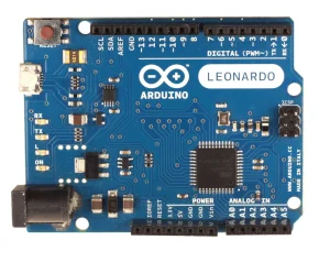
Input voltages are usually measured against a reference voltage that matches the voltage used to power the Arduino. This is convenient, as the Arduino is commonly the voltage source for sensing attached switches and potentiometers. It is possible to set a different reference voltage inside the Arduino, using AnalogReference(). This approach has some limitations, not the least of which is the lack of uniformity across the range of Arduinos and clones. This project began on an Arduino Mega clone, was installed on genuine Arduino Pro units for the final product and was moved to a Duinotech Nano for one of the interfaces. The second round of hardware has spent some time installed on 3.3v Duinotech ESP32s and a 3.3v Arduino Nano 33 BLE Sense (the sense has an optional 12 bit resolution but uses 10 bits for compatibility).

Lets’s look at the available reference voltages for the family of boards that I have used for the first round. Setting anaglogReference(INTERNAL) gives different results on different boards, some values are only available on Mega boards and the standard value differs between 5v and 3.3v versions of the same boards.

Arduino AVR style internal reference voltages: 
5V (5V power supply) or 3.3V (3.3V power supply)
INTERNAL: 1.1 volts on the ATmega168 or ATmega328P and 2.56 volts on the ATmega32U4 and ATmega8 (not available on the Arduino Mega)
INTERNAL1V1: a built-in 1.1V reference (Arduino Mega only)
INTERNAL2V56: a built-in 2.56V reference (Arduino Mega only)

So why not maximise the voltage available for measurement by using a known resistance similar in value to my length of nichrome? Because that would be very dangerous for my Arduino. The nichrome in the bow forms a loop when the two strands are bridged by a metal contact, so the total resistance would be < ~14Ω when in use (you won’t usually use the very ends of the bow, so you won’t see the full 16Ω). Even if we double that and use a 25Ω resistor, with a 5v source that is is ~200mA (1W @ 5v!). I’ve looked through the specifications for a few models of Arduino, and they have all had a 40mA maximum for IO pins. So how do we do it safely?

Safe sensing

Connecting a constant current source to the Arduino.

We can measure low resistances safely using an external constant current source. R = V / I, so with a known voltage and current we can measure resistance without presenting a risk to the Arduino. The LM317 regulator shown in the diagram provides a known 104mA. We can round this down to 100mA (0.01A) and see that R = 10V. My 14Ω usable resistance range is now a manageable voltage range of 0 – 1.4V of 1.6V total range measured against 5V. That immediately improves the 5V Arduinos measurement resolution to ~287 of ~328. The hardware will be re re-implemented on newer 3.3V modules which improves the Arduinos performance to ~434 of ~496. The 3.3V Nano 33 BLE SENSE has an optional 12 bit mode (0 – 4095) that improves the bow reading accuracy again to ~1736 of ~1984.

Making it Better

There are some easy ways to make the hardware better – the most obvious being altering the current source, but these modules are already built and I’d like them to be useful for other low resistance tasks, so they’ll stay at 100mA for now. There is, however, a simple way of drastically improving the apparent resolution of a hardware sampling system without touching the hardware at all:

Next installment: oversampling

LM317 modules in action:

Bow electronics package. The LM317 is visible on the bottom right.
Another electronics package for the body of the violin, to sense a nichrome replacement for one of the violin strings. The LM317 and 12Ω resistor are visible on the middle right.

Posted on

Using Inkscape (and other free products) to run a CNC mill.

Inkscape is a popular, free and easy to use vector graphics editor. It won’t give you the powerful part manipulation features of a CAD program – but it is a comfortable working environment for artists or designers that may be more used to Illustrator, Canvas, Xara or similar art packages. The current version of Inkscape (.92) comes with a plugin for generating Gcode, a popular language for running small CNC mills. The process for getting from artwork to code and then to the mill is not well documented and can be very confusing for a new user, so I’m going to explain the process step-by-step in the hope that others can find it useful.

The Preparation

Orientation points and the tool library.

In order for the Gcode plugin to generate code, it needs to know where to place the origin (zero X,Y) of your drawing and how deep you need to cut. These values are set using the orientation points. You can move these points to other areas of the document, but be careful not to accidentally group them or edit them when you think you have another part selected or they may stop working. You can delete them and re-generate them at any time if they become broken.

Select ‘Orientation points’ from the Extensions menu

Markers for 0,0 and 100,0 will appear at the bottom of your document. This is an excellent time to check that 100,0 on the Orientation points matches 100 on your X ruler at the top of the page. It can be very confusing if your document measurements are set in pixels (or something else) and your orientation points are in mm. The very last number, in this case -0.25, is the total depth of the cut you wish to perform. You can add more orientation point sets on other layers for different cut levels, but I won’t go into that now. You can edit the depth by clicking on it as if your were editing a normal Inkscape text object.
Next we need to tell Inkscape about your tools and how you want to cut with them.

Select ‘Tools library’ from the Extensions menu.

For engraving work, you will need a cone cutter. For simple jobs with only one tool this selection does not really matter, but it helps to give tools their proper names if you come back to this file after some time has passed.

Click on the text values to edit them as if they were normal Inkscape text objects. Set the speed to something sensible. The depth step will generate layers of cuts until the final depth set in the orientation points is reached. For example, if I had set a depth of 5mm in the Orientation points and 1mm in Depth step, the tool would cut the path 5 times, lowering by 1mm each time. My total depth is only -0.25mm so a step of 1mm will only produce one layer of cuts.
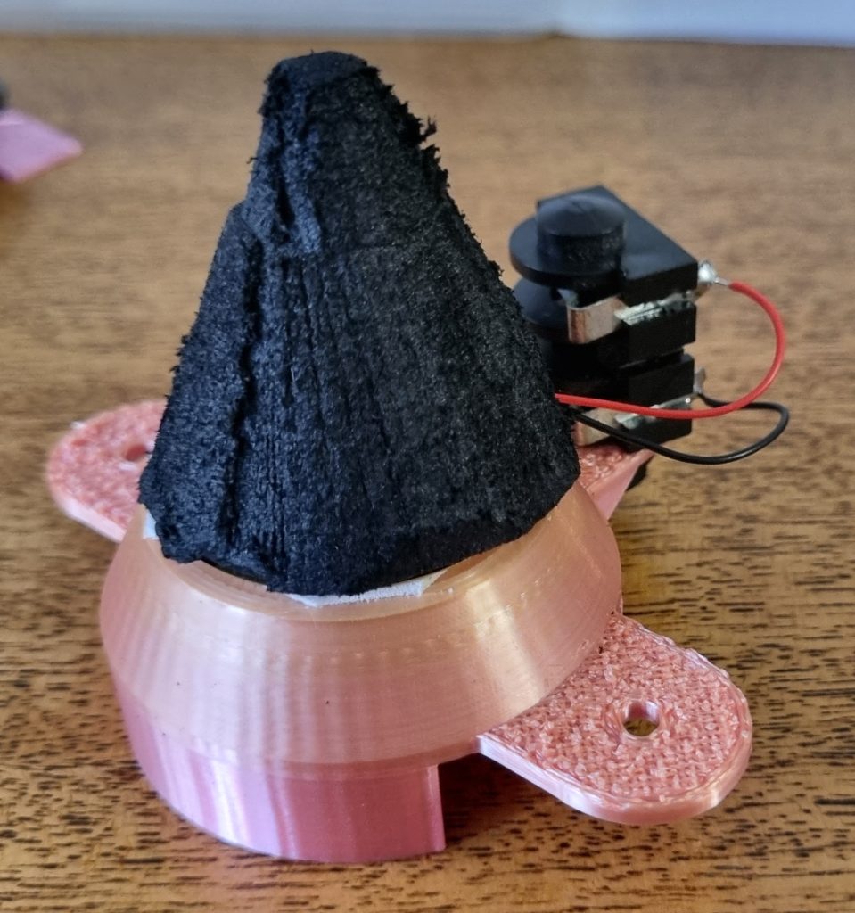
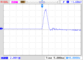
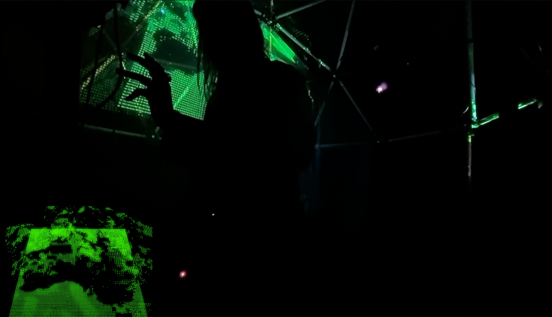
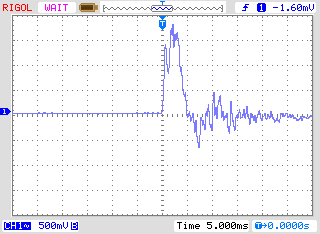
The tool description will ‘helpfully’ appear right over the top of your work, so just drag it off to the side to get it out of the way.

Generating the code.

The Gcode generator has some restrictions. Items MUST be paths and they must not be part of a group. The status line at the bottom of the screen will tell you if you have any groups in your selection. Fonts must be turned into paths! I usually make a copy of my work in a separate, locked, hidden layer before turning it all into paths for the plugin.

You are ready to select ‘Path to Gcode’ from the Extensions menu.

Open the Preferences tab; set the name of your output file and, importantly, your safe travel height! I usually leave on ‘Add numeric suffix’ which just adds a version number to the end of every new file, keeping the old ones in place. I recommend this because it is very easy to forget to update your file name and accidentally overwrite the last project you were working on.

Now flip back to the first tab and hit Apply! Note: you must be on this tab when you hit Apply. It won’t work if any of the other tabs are selected. I guess it must be a restriction in the way plugins are written for Inkscape.

Check the Gcode

This is OpenSCAM, known in later versions as Camotics. The later versions look slicker but have removed some functionality that I liked. It can show you the surface of your finished job and the paths your tools will take over the surface.

Rapids are shown in red, the cut path is in green. This tool is especially useful for calculating how long your job will take to cut at various speeds and depth slices.

Level the Gcode

Autoleveller is a simple but invaluable piece of software that makes PCB or artwork engraving a reliable, repeatable process. It modifies your Gcode to include instructions for probing the surface of your work, recording the variations in height and applying those variations to your cutting job. If PCBs are your focus get this software or something similar without delay.

A simple Java interface. This version is a bit old, but so is my Java. I often work with boxes that are cast with curved edges, so I start the probe job 5mm in from the edge (the X and Y entries), and shorten the X Length and Y Length by a similar amount to avoid the curve. I also raise the Probe Depth from 1mm to 5mm so I spend less time setting the mill up before I start probing. It can generate code for LinuxCNC, Mach3 or TurboCNC. Depth probes don’t have to be expensive or complicated. I glued a microswitch to the end of a pencil shaft that fits over my cutting bit. It works perfectly well and cost me $2.

Posted on

Making keys for the uniform keyboard

It was immediately obvious that painting over the top of re-shaped keys was just not going to be good enough. The existing keyboard I had been shown was functional but looked like a mess. These keyboards would probably see heavy use by students so I needed something very durable that also felt natural. It’s hard enough learning a new way of playing a keyed instrument without the distraction of paint coming off under your fingers.

I decided to re-cast the tops of the raised keys (previously the sharps and flats) in solid white resin. This increases the mass of the key a little, but that is not a drawback. The more expensive Korgs that use this keybed have weights installed to give them a better feel and even out the stronger spring response of the shorter keys. The extra weight of my solid tops is improving the keyboard!

Posted on

Bilinear Uniform Chromatic Keyboard

This is an interesting project. I’ve just been commissioned to alter a Korg Triton LE keyboard to the bilinear uniform chromatic keyboard standard.  It fairly obvious to anyone who has studied keyed instruments that the traditional keyboard is exactly the sort of mess that you end up with when you extend an interface far past what is was originally meant to do. We can’t undo the unholy dog’s breakfast that is tempered tuning, but at least we can address the crazy lopsided way we approach the piano keyboard. If you are interested in how it works, there is a great explanation here.

All of the previously ‘white’ keys need to be trimmed to a symmetrical shape and widened. There are more ‘black’ keys than before, so I’ll have to order some in as parts. Luckily the Triton was a very popularkeyboard, so parts are easy to find. Shaping and re-casting the keys will the tricky part.The Triton is very easy to take apart and the screws are large and mostly restricted to two sizes, making eventual reassembly much easier. After lifting off the bottom plate the whole keybed comes out as one unit. The keys clip in and out of the bed easily. I’ve arranged the ‘black’ keys where I need them, but five more need to be ordered to fill the gap.

That’s the easy part. I’ve measured the keys and laid out my replacement white key in Solvespace. Now it’s time to make a mold and start cutting them up.