Using Inkscape (and other free products) to run a CNC mill.
Inkscape is a popular, free and easy to use vector graphics editor. It won’t give you the powerful part manipulation features of a CAD program – but it is a comfortable working environment for artists or designers that may be more used to Illustrator, Canvas, Xara or similar art packages. The current version of Inkscape (.92) comes with a plugin for generating Gcode, a popular language for running small CNC mills. The process for getting from artwork to code and then to the mill is not well documented and can be very confusing for a new user, so I’m going to explain the process step-by-step in the hope that others can find it useful.
The Preparation
Orientation points and the tool library.
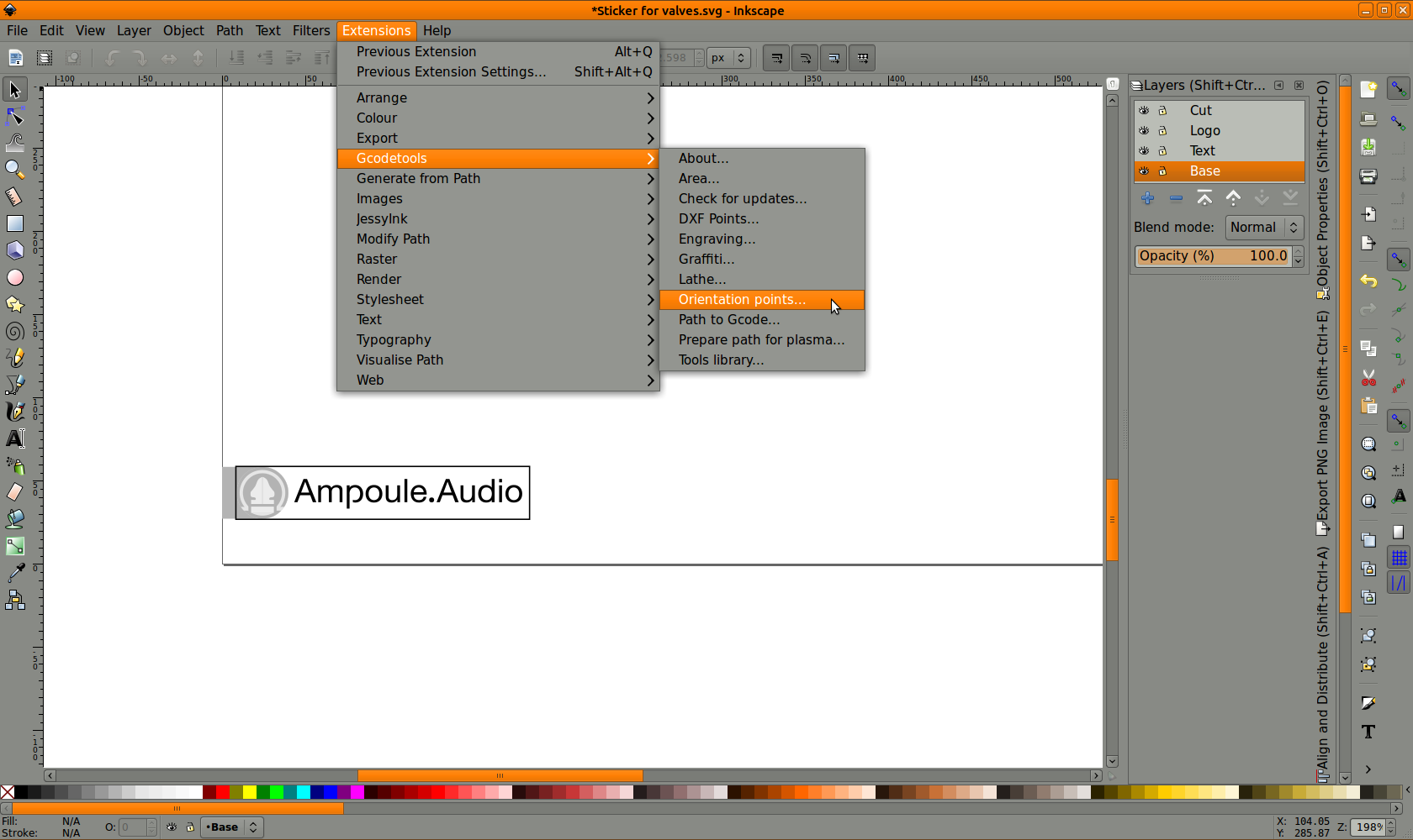
In order for the Gcode plugin to generate code, it needs to know where to place the origin (zero X,Y) of your drawing and how deep you need to cut. These values are set using the orientation points. You can move these points to other areas of the document, but be careful not to accidentally group them or edit them when you think you have another part selected or they may stop working. You can delete them and re-generate them at any time if they become broken.
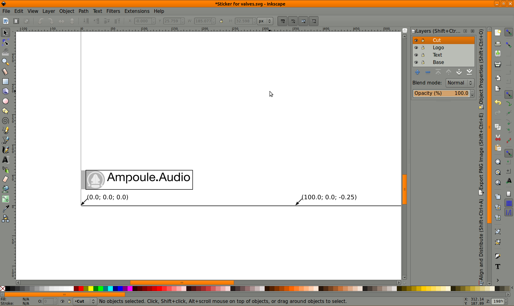
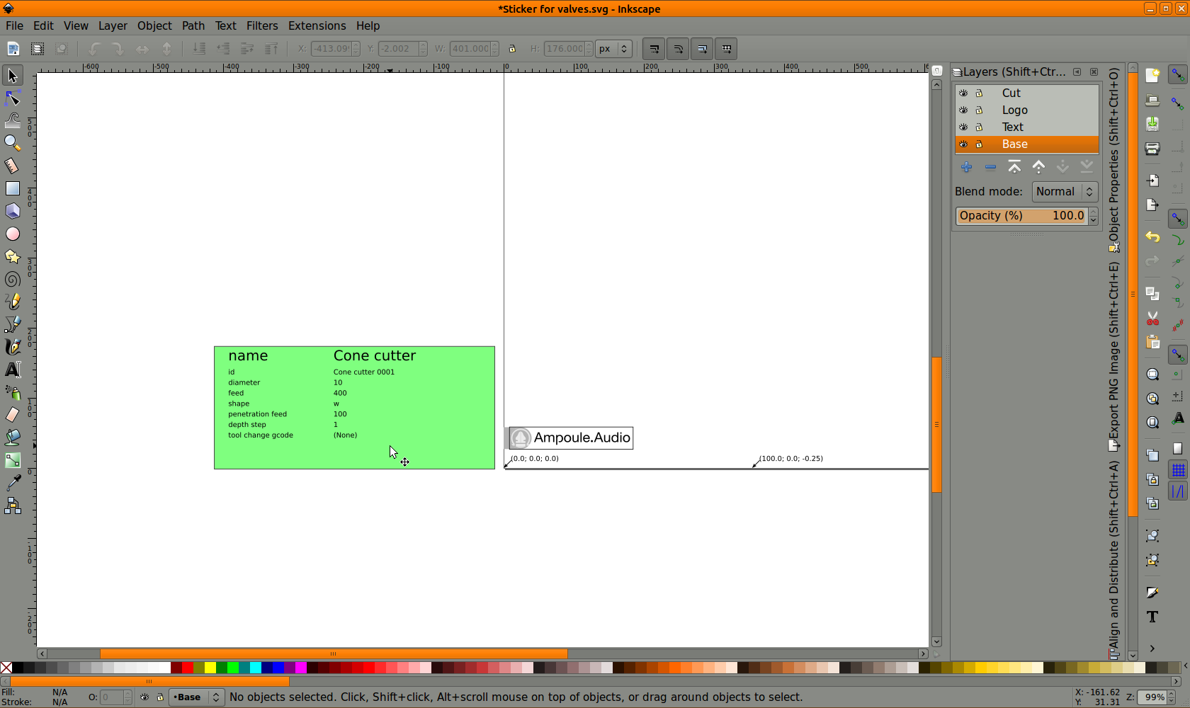
Select ‘Orientation points’ from the Extensions menuMarkers for 0,0 and 100,0 will appear at the bottom of your document. This is an excellent time to check that 100,0 on the Orientation points matches 100 on your X ruler at the top of the page. It can be very confusing if your document measurements are set in pixels (or something else) and your orientation points are in mm. The very last number, in this case -0.25, is the total depth of the cut you wish to perform. You can add more orientation point sets on other layers for different cut levels, but I won’t go into that now. You can edit the depth by clicking on it as if your were editing a normal Inkscape text object.
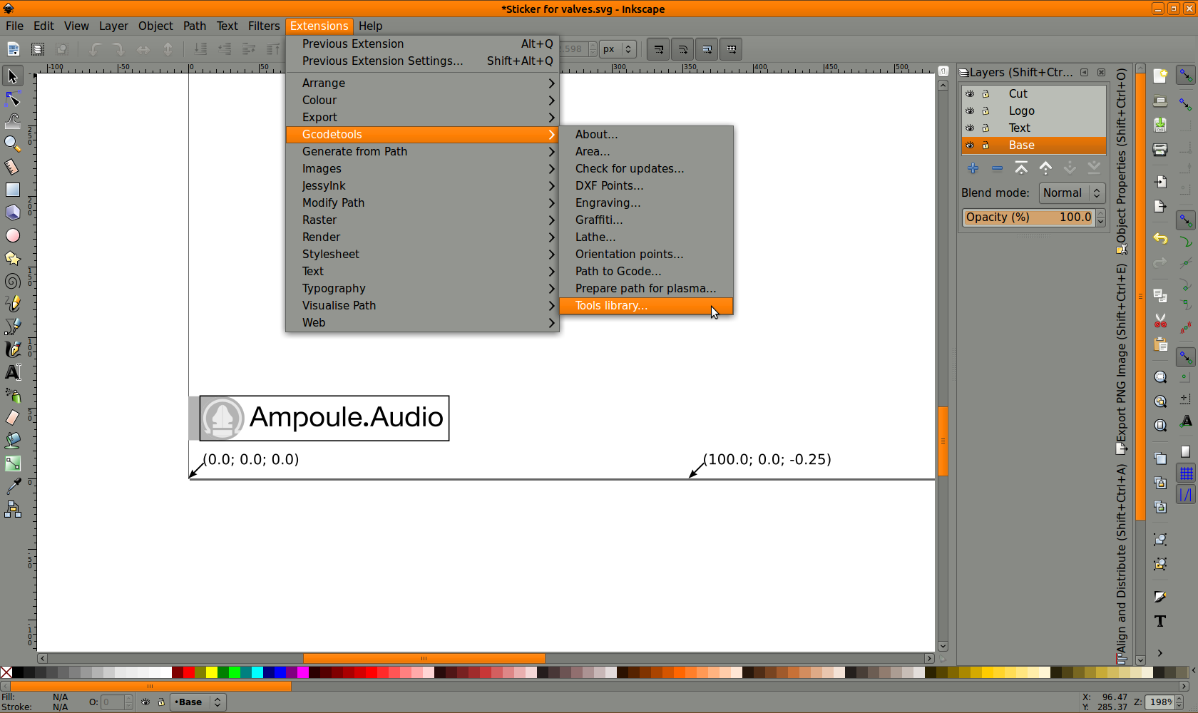
Next we need to tell Inkscape about your tools and how you want to cut with them.
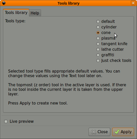
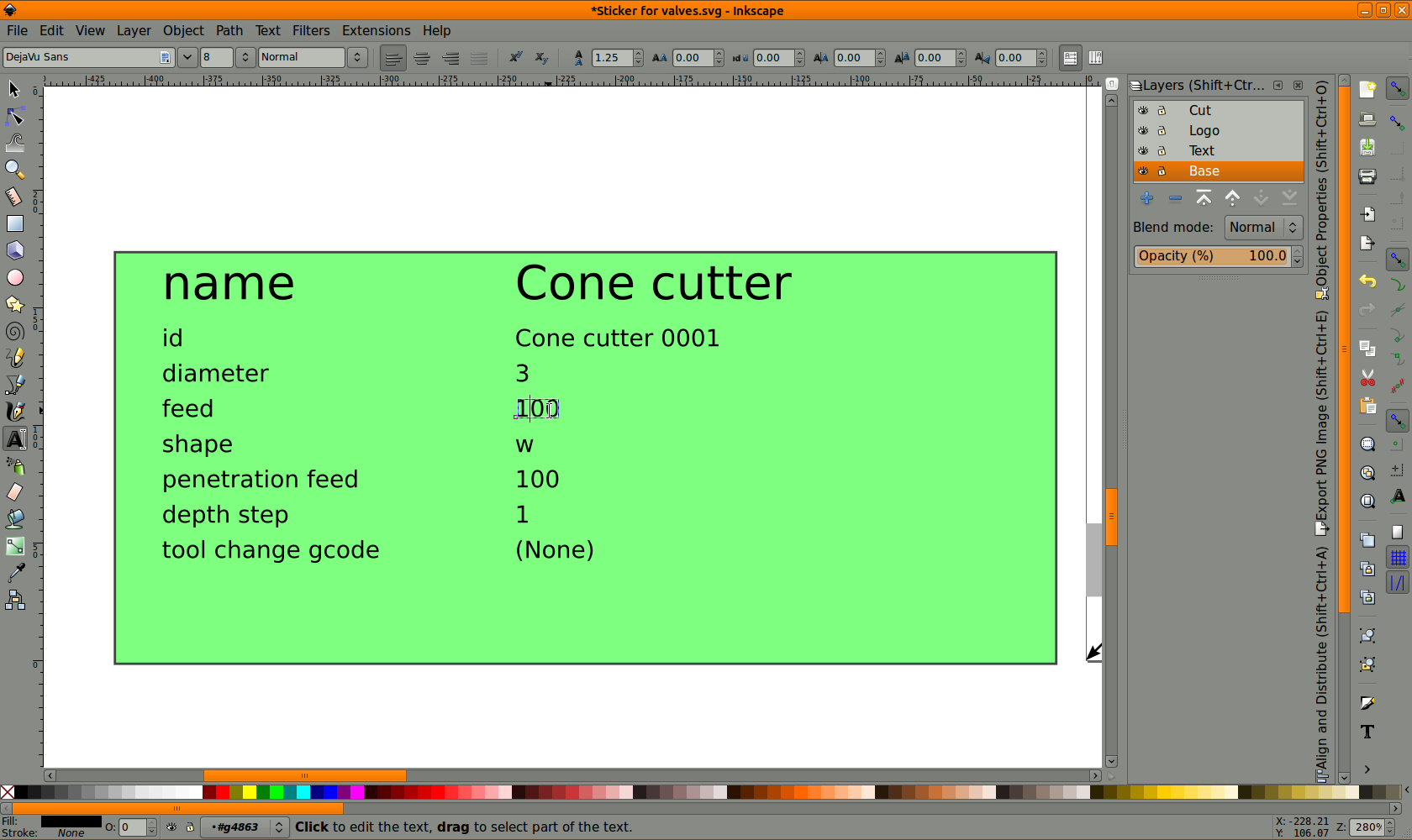
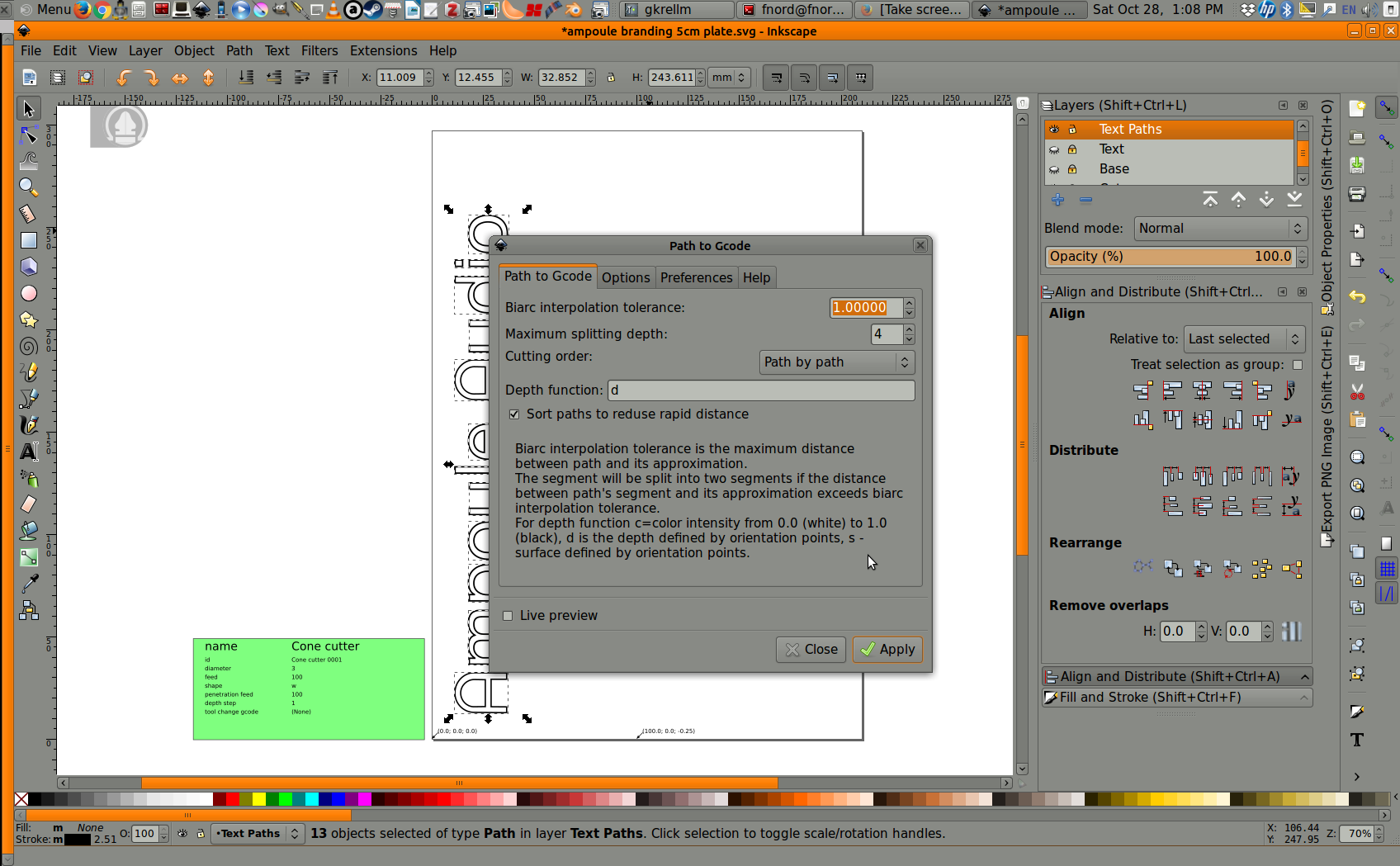
Select ‘Tools library’ from the Extensions menu.For engraving work, you will need a cone cutter. For simple jobs with only one tool this selection does not really matter, but it helps to give tools their proper names if you come back to this file after some time has passed.Click on the text values to edit them as if they were normal Inkscape text objects. Set the speed to something sensible. The depth step will generate layers of cuts until the final depth set in the orientation points is reached. For example, if I had set a depth of 5mm in the Orientation points and 1mm in Depth step, the tool would cut the path 5 times, lowering by 1mm each time. My total depth is only -0.25mm so a step of 1mm will only produce one layer of cuts.The tool description will ‘helpfully’ appear right over the top of your work, so just drag it off to the side to get it out of the way.
Generating the code.
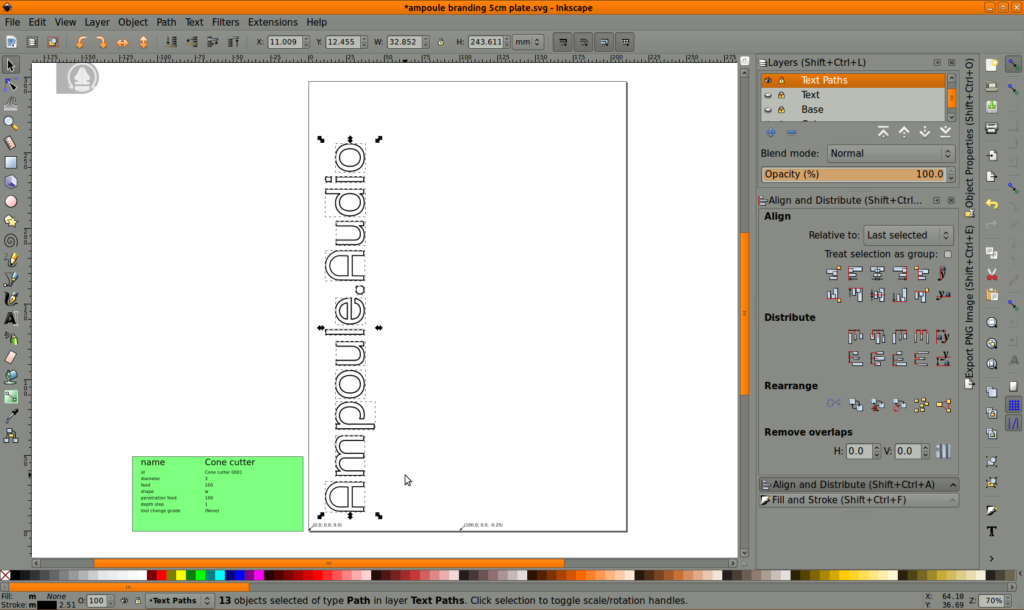
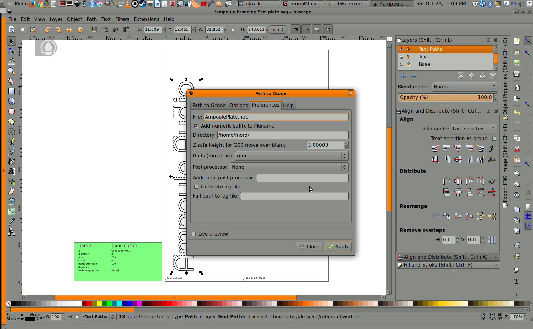
The Gcode generator has some restrictions. Items MUST be paths and they must not be part of a group. The status line at the bottom of the screen will tell you if you have any groups in your selection. Fonts must be turned into paths! I usually make a copy of my work in a separate, locked, hidden layer before turning it all into paths for the plugin.You are ready to select ‘Path to Gcode’ from the Extensions menu.Open the Preferences tab; set the name of your output file and, importantly, your safe travel height! I usually leave on ‘Add numeric suffix’ which just adds a version number to the end of every new file, keeping the old ones in place. I recommend this because it is very easy to forget to update your file name and accidentally overwrite the last project you were working on.Now flip back to the first tab and hit Apply! Note: you must be on this tab when you hit Apply. It won’t work if any of the other tabs are selected. I guess it must be a restriction in the way plugins are written for Inkscape.
Check the Gcode
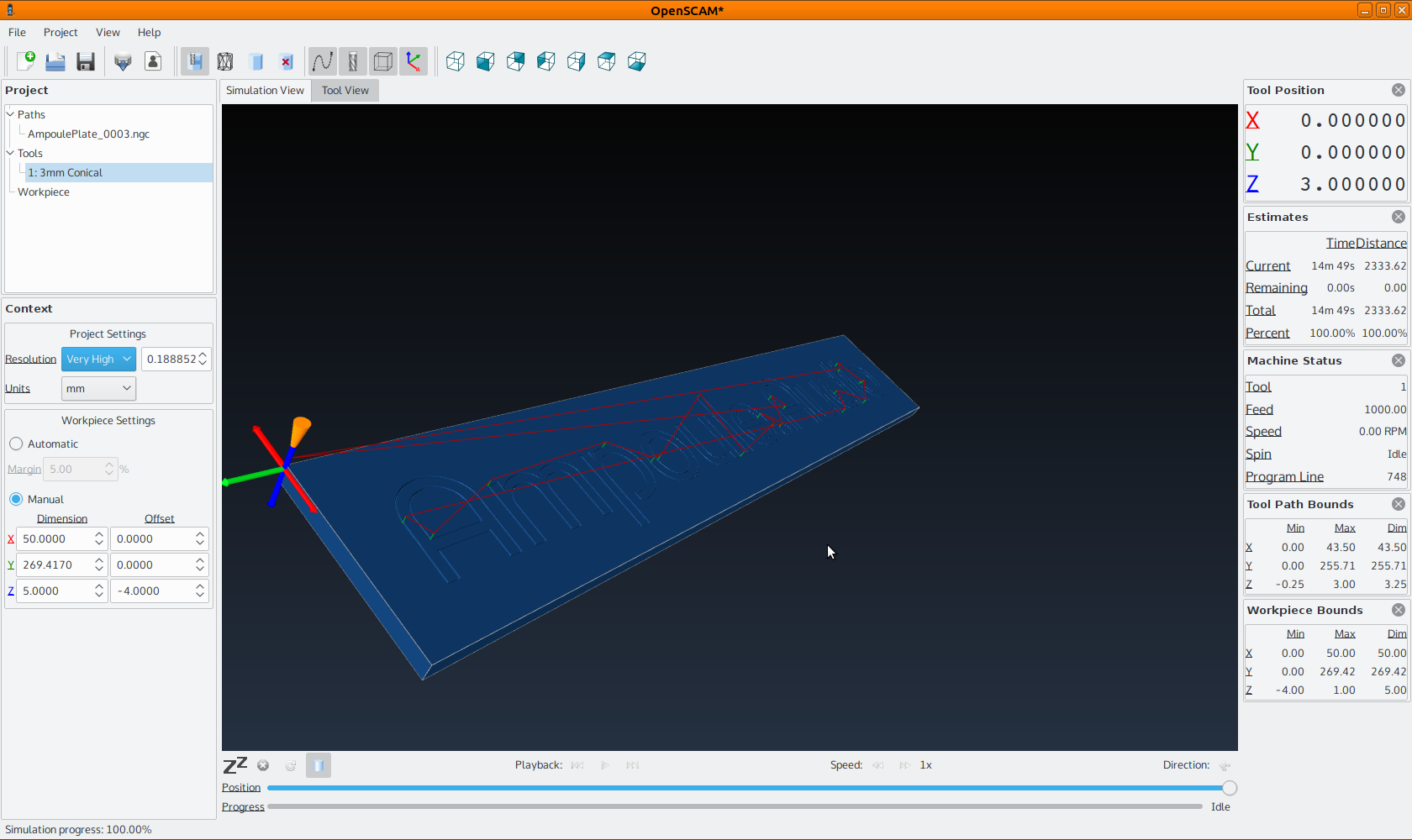
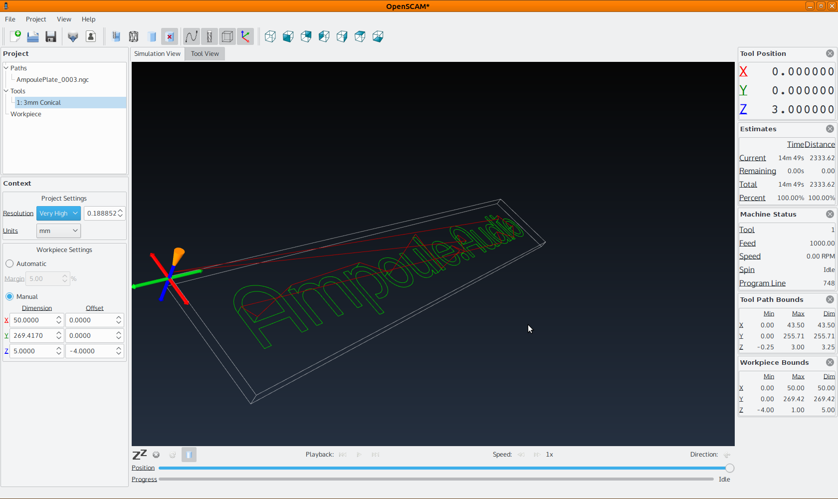
This is OpenSCAM, known in later versions as Camotics. The later versions look slicker but have removed some functionality that I liked. It can show you the surface of your finished job and the paths your tools will take over the surface.Rapids are shown in red, the cut path is in green. This tool is especially useful for calculating how long your job will take to cut at various speeds and depth slices.
Level the Gcode
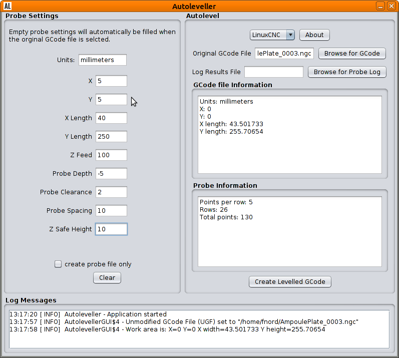
Autoleveller is a simple but invaluable piece of software that makes PCB or artwork engraving a reliable, repeatable process. It modifies your Gcode to include instructions for probing the surface of your work, recording the variations in height and applying those variations to your cutting job. If PCBs are your focus get this software or something similar without delay.
A simple Java interface. This version is a bit old, but so is my Java. I often work with boxes that are cast with curved edges, so I start the probe job 5mm in from the edge (the X and Y entries), and shorten the X Length and Y Length by a similar amount to avoid the curve. I also raise the Probe Depth from 1mm to 5mm so I spend less time setting the mill up before I start probing. It can generate code for LinuxCNC, Mach3 or TurboCNC. Depth probes don’t have to be expensive or complicated. I glued a microswitch to the end of a pencil shaft that fits over my cutting bit. It works perfectly well and cost me $2.