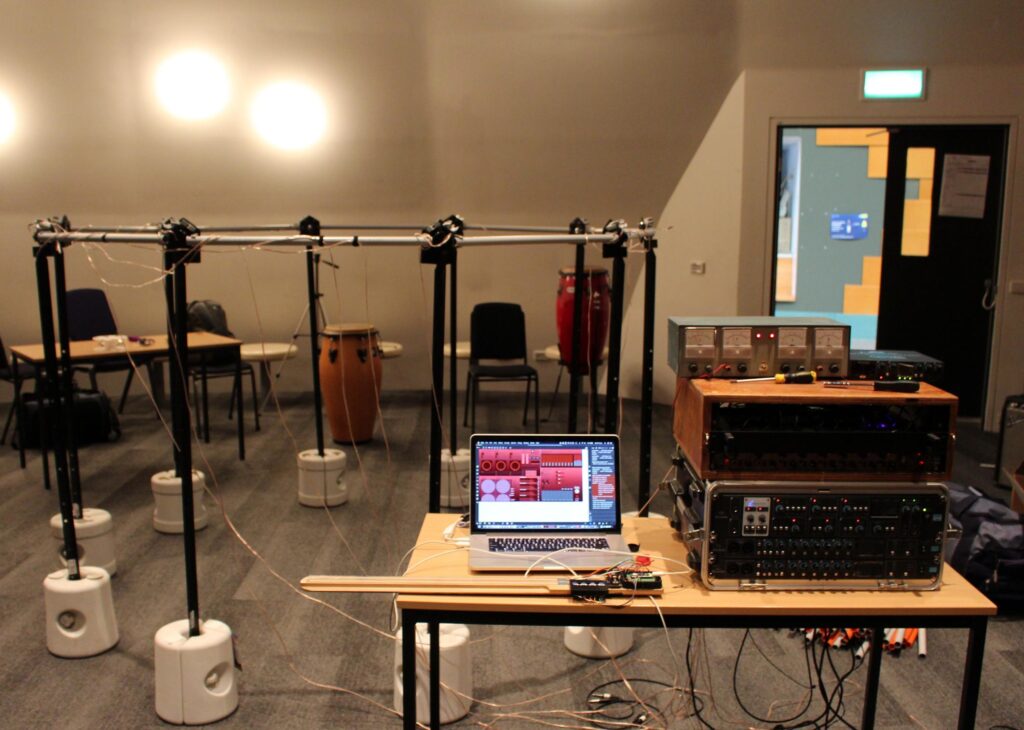
This project seemed fairly simple when I started designing it around March 2020. 26 Speakers, 26 amplifiers, an ambisonic decoder and some simple arduino based controllers. It got out of hand very quickly and although I am happy with how the project has come together, I have spent more time than I would like to admit wanting to set the whole thing on fire and forgetting that I ever wanted this thing to exist.
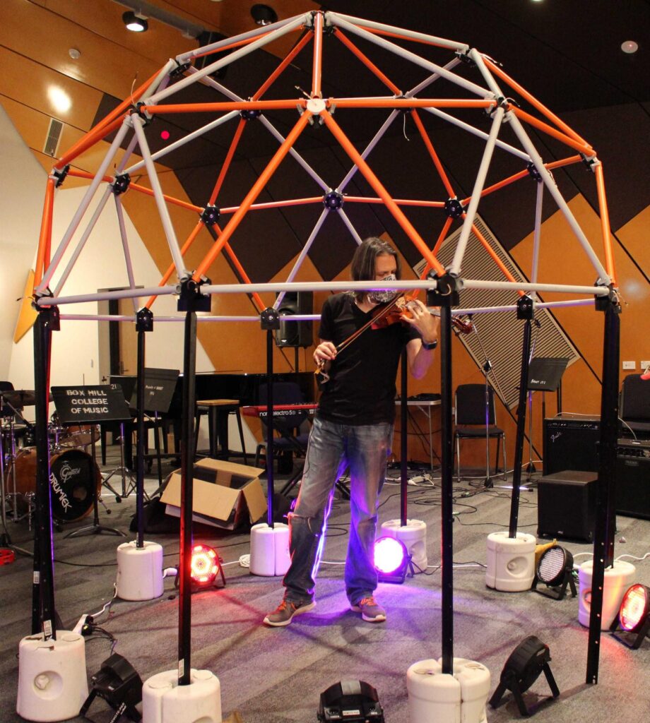
The Dome Structure
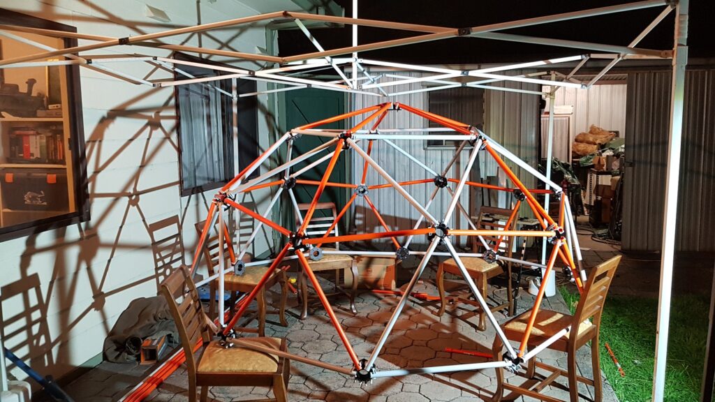
It’s what everyone sees first – it defines the whole project. It turned out to be the easiest part.
The hubs are 3D printed from PLA using a very cheap little 3D printer from Cocoon Products. It’s branded ‘Balco’ and I think that this model was once sold through Aldi. Although it was cheap it has some features that I think a 3D printer must have in order to be genuinely useful.
- A heated bed – if you print in ABS or other less forgiving mediums than PLA you will need a heated bed. Without one your prints will curl up from contraction of the hot plastic while the job is still being printed. Sometimes it still will anyway. Ambient temperature can have a big effect on the quality of your prints. On cold nights I’ve built boxes from styrofoam, cardboard and clear polycarbonate around to printer to keep the heat from the bed escaping. A ready-made fully enclosed printer would be great, but is three times more expensive than my Balco.
- Standalone operation from an SD Card – I have CNC mills that are driven straight from the computer (via the parallel port). It’s great to have a cool animated display (from Linux CNC), but it requires me to have a monitor, computer, keyboard and mouse for each mill. Either that or have my laptop tied up for four hours during a cut. It’s great to just load a GCode file onto the SD Card, open it from the touch screen and walk away.
- Moving bed gantry design – this is nice because the bed doesn’t move beyond the boundaries of the printer base. For messy people like me, this means that your printer won’t push things off the bench. (My CNC mills will do this all the time if I’m careless).
- A cool little touch screen with utility functions built in – filament exchange, homing and bed-leveling are all built into the unit. This saves a lot of time and fiddling around.
Files are prepared for the 3D printer using the free software package ‘Ultimaker Cura‘. It won’t help you with modifying your designs, though it can expand or shrink the size – a function I’ve used in very small increments to make the caps fit better on my hubs.
The Dome Components
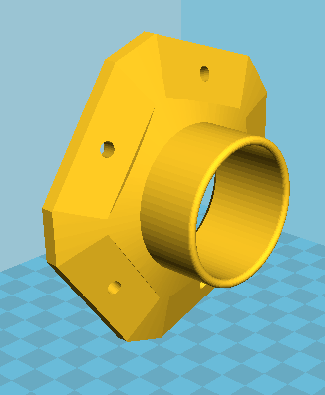
Five sided hub 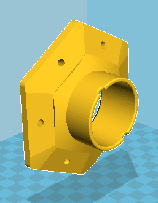
Six sided hub 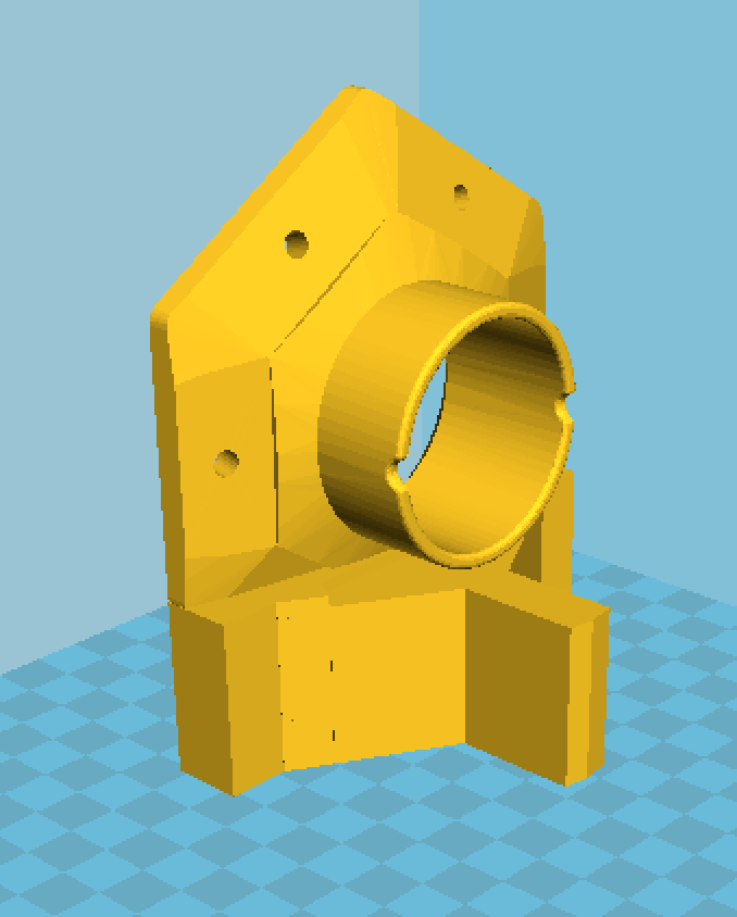
Base ring hub with a slot for a steel picket 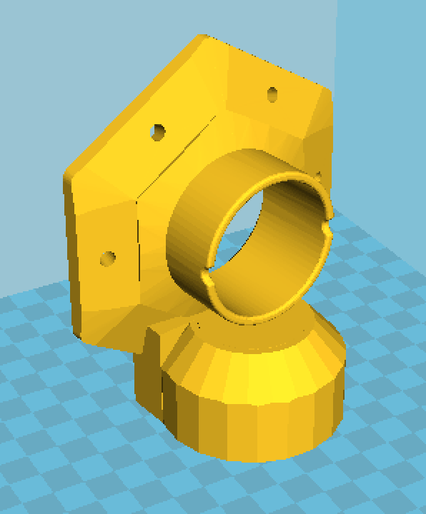
Base ring hub with round hole for conduit legs
My original plans were to test print the dome using PLA (it’s faster and more forgiving to print) and, after verifying the design, to reprint the whole thing in ABS for better strength. I never had to. The dome has been set up several times in differing locations, been left out in a thunderstorm, and has undergone rapid unplanned disassembly several times (the first few times we tried to raise a finished dome onto its legs. I’ve had to re-print parts due to breakage only four five six times so far).
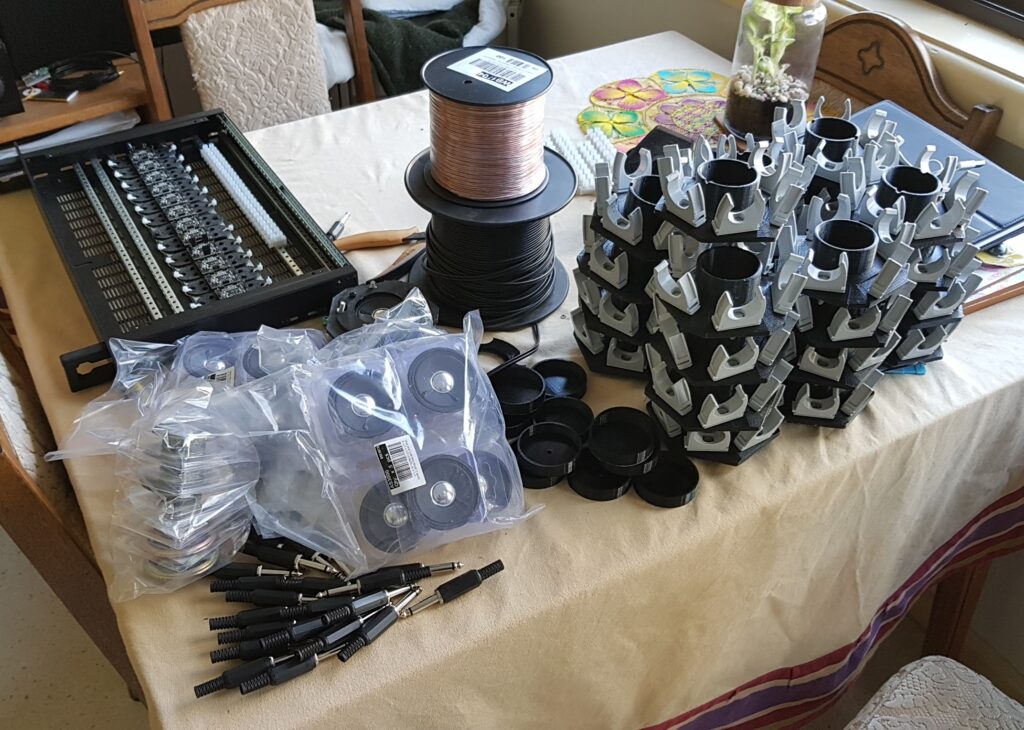
Each hub contains a single 6cm speaker held in place with a printed ring. They are quite small and don’t have a lot of power behind them, so they can’t handle low frequencies. Low frequencies are not very important for directional audio, so a single subs unit can handle the low frequency audio.